


COMBUSTION LEAKAGE TEST (WITHOUT
PRESSURE TESTER)
DO NOT WASTE reusable coolant. If the solution
is clean, drain the coolant into a clean container for
reuse.
WARNING: DO
NOT
REMOVE
THE
CYLINDER
BLOCK DRAIN PLUGS OR LOOSEN THE RADIATOR
DRAINCOCK WITH THE SYSTEM HOT AND UNDER
PRESSURE. SERIOUS BURNS FROM COOLANT
CAN OCCUR.
Drain sufficient coolant to allow for thermostat
removal. Refer to Thermostat Replacement. Discon-
nect the water pump drive belt.
Disconnect the upper radiator hose from the ther-
mostat housing. Remove the housing and thermostat.
Install the thermostat housing.
Add coolant to the radiator to bring the level to
within 6.3 mm (1/4 in) of the top of the thermostat
housing.
CAUTION: Avoid overheating. Do not operate the
engine for an excessive period of time. Open the
draincock immediately after the test to eliminate
boil over of coolant.
Start the engine and accelerate rapidly three times
(to approximately 3000 rpm) while observing the
coolant. If internal engine combustion gases are leak-
ing into the cooling system, bubbles will appear in
the coolant. If bubbles do not appear, there is no
internal combustion gas leakage.
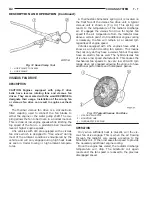
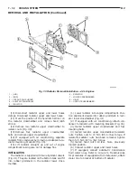
VISCOUS FAN DRIVE
LEAKS
Viscous fan drive operation is not affected by small
oil stains near the drive bearing. If leakage appears
excessive, replace the fan drive unit.
TESTING
If the fan assembly free-wheels without drag (the
fan blades will revolve more than five turns when
spun by hand), replace the fan drive. This spin test
must be performed when the engine is cool.
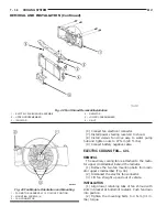
For the following test, the cooling system must be
in good condition. It also will ensure against exces-
sively high coolant temperature.
WARNING: BE SURE THAT THERE IS ADEQUATE
FAN BLADE CLEARANCE BEFORE DRILLING.
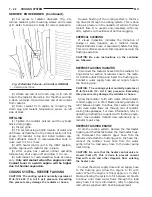
(1) Drill a 3.18-mm (1/8-in) diameter hole in the
top center of the fan shroud.
(2) Obtain a dial thermometer with an 8 inch stem
(or equivalent). It should have a range of -18°-to-
105°C (0°-to-220° F). Insert thermometer through the
hole in the shroud. Be sure that there is adequate
clearance from the fan blades.
(3) Connect a tachometer and an engine ignition
timing light (timing light is to be used as a strobe
light).
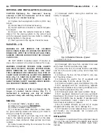
(4) Block the air flow through the radiator. Secure
a sheet of plastic in front of the radiator (or air con-
ditioner condenser). Use tape at the top to secure the
plastic and be sure that the air flow is blocked.
(5) Be sure that the air conditioner (if equipped) is
turned off.
WARNING: USE EXTREME CAUTION WHEN THE
ENGINE IS OPERATING. DO NOT STAND IN A
DIRECT LINE WITH THE FAN. DO NOT PUT YOUR
HANDS NEAR THE PULLEYS, BELTS OR FAN. DO
NOT WEAR LOOSE CLOTHING.
(6) Start the engine and operate at 2400 rpm.
Within ten minutes the air temperature (indicated on
the dial thermometer) should be up to 88° C (190° F).
Fan drive engagement should have started to occur
at between 74° to 82° C (165° to 180° F). Engage-
ment is distinguishable by a definite increase in fan
flow noise (roaring). The timing light also will indi-
cate an increase in the speed of the fan.
(7) When the air temperature reaches 88° C (190°
F), remove the plastic sheet. Fan drive disengage-
ment should have started to occur at between 57° to
79° C (135° to 175° F). A definite decrease of fan
flow noise (roaring) should be noticed. If not, replace
the defective viscous fan drive unit.
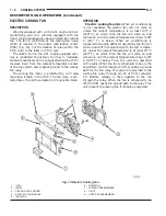
ELECTRIC COOLING FAN
ELECTRIC COOLING FAN AND RELAY DIAGNOSIS
NOTE: Refer to Electrical Group 8W for electric
cooling fan and relay circuit schematic.
The powertrain control module (PCM) will enter a
diagnostic trouble code (DTC) in memory if it detects
a problem in the auxiliary cooling fan relay or circuit.
Refer to Group 25, Emission Control Systems for cor-
rect DTC retrieval procedures.
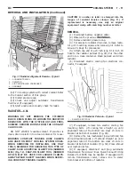
If the electric cooling fan is inoperative, check the
15A fuse in the junction block and the 40A fuse in
the Power Distribution Center (PDC) with a 12 volt
test lamp or DVOM. Refer to the inside of the PDC
cover for the exact location of the fuse. If fuses are
o.k., refer to Group 8W for electric cooling fan and
relay circuit schematic.
XJ
COOLING SYSTEM
7 - 19
DIAGNOSIS AND TESTING (Continued)
Summary of Contents for Cherokee 2000
Page 4: ......
Page 36: ......
Page 96: ...Fig 105 Gear Tooth Contact Patterns 3 60 TUBE 181 AND 186 FBI AXLE XJ ADJUSTMENTS Continued...
Page 100: ...Installer D 144 Installer W 262 3 64 TUBE 181 AND 186 FBI AXLE XJ SPECIAL TOOLS Continued...
Page 134: ...Fig 79 Gear Tooth Contact Patterns 3 98 194 RBI AXLE XJ ADJUSTMENTS Continued...
Page 166: ...Fig 59 Gear Tooth Contact Patterns 3 130 8 1 4 REAR AXLE XJ ADJUSTMENTS Continued...
Page 215: ...Fig 8 Clutch Components And Inspection XJ CLUTCH 6 5 DIAGNOSIS AND TESTING Continued...
Page 226: ......
Page 231: ...Fig 8 Clutch Components And Inspection XJ CLUTCH 6 5 DIAGNOSIS AND TESTING Continued...
Page 242: ......
Page 284: ......
Page 300: ......
Page 372: ......
Page 376: ......
Page 382: ......
Page 404: ......
Page 412: ......
Page 416: ......
Page 430: ......
Page 444: ......
Page 448: ......
Page 468: ......
Page 482: ......
Page 500: ......
Page 508: ......
Page 520: ......
Page 526: ......
Page 532: ......
Page 540: ......
Page 550: ......
Page 647: ...Fig 16 2 5L Engine XJ 8W 90 CONNECTOR LOCATIONS 8W 90 23 DESCRIPTION AND OPERATION Continued...
Page 648: ...Fig 17 4 0L Engine 8W 90 24 8W 90 CONNECTOR LOCATIONS XJ DESCRIPTION AND OPERATION Continued...
Page 649: ...Fig 18 4 0L Engine XJ 8W 90 CONNECTOR LOCATIONS 8W 90 25 DESCRIPTION AND OPERATION Continued...
Page 662: ...Fig 31 Liftgate 8W 90 38 8W 90 CONNECTOR LOCATIONS XJ DESCRIPTION AND OPERATION Continued...
Page 666: ......
Page 810: ......
Page 826: ...Fig 6 Frame Dimensions 13 8 FRAME AND BUMPERS XJ SPECIFICATIONS Continued...
Page 828: ......
Page 1316: ......
Page 1328: ......
Page 1353: ...Fig 3 Hood Components XJ BODY 23 25 REMOVAL AND INSTALLATION Continued...
Page 1396: ...WELD LOCATIONS UPPER COWL 23 68 BODY XJ SPECIFICATIONS Continued...
Page 1397: ...UPPER COWL XJ BODY 23 69 SPECIFICATIONS Continued...
Page 1398: ...COWL 23 70 BODY XJ SPECIFICATIONS Continued...
Page 1399: ...A PILLAR XJ BODY 23 71 SPECIFICATIONS Continued...
Page 1400: ...A PILLAR 23 72 BODY XJ SPECIFICATIONS Continued...
Page 1401: ...A PILLAR XJ BODY 23 73 SPECIFICATIONS Continued...
Page 1402: ...A PILLAR 23 74 BODY XJ SPECIFICATIONS Continued...
Page 1403: ...B PILLAR XJ BODY 23 75 SPECIFICATIONS Continued...
Page 1404: ...D PILLAR 23 76 BODY XJ SPECIFICATIONS Continued...
Page 1405: ...FUEL FILLER OPENING XJ BODY 23 77 SPECIFICATIONS Continued...
Page 1406: ...CARGO AREA FLOOR PAN 23 78 BODY XJ SPECIFICATIONS Continued...
Page 1407: ...ROOF AND D PILLAR XJ BODY 23 79 SPECIFICATIONS Continued...
Page 1408: ...LIFTGATE OPENING 23 80 BODY XJ SPECIFICATIONS Continued...
Page 1409: ...ROOF XJ BODY 23 81 SPECIFICATIONS Continued...
Page 1410: ...ROOF 23 82 BODY XJ SPECIFICATIONS Continued...
Page 1411: ...FRAME RAIL XJ BODY 23 83 SPECIFICATIONS Continued...
Page 1412: ...FRAME RAIL 23 84 BODY XJ SPECIFICATIONS Continued...
Page 1413: ...FRAME RAIL XJ BODY 23 85 SPECIFICATIONS Continued...
Page 1414: ...FRAME RAIL 23 86 BODY XJ SPECIFICATIONS Continued...
Page 1415: ...REINFORCEMENT XJ BODY 23 87 SPECIFICATIONS Continued...
Page 1416: ...FRONT INNER FENDER 23 88 BODY XJ SPECIFICATIONS Continued...
Page 1417: ...FRONT INNER FENDER AND RADIATOR CLOSURE PANEL XJ BODY 23 89 SPECIFICATIONS Continued...
Page 1418: ...REINFORCEMENT 23 90 BODY XJ SPECIFICATIONS Continued...
Page 1419: ...FRONT FENDER XJ BODY 23 91 SPECIFICATIONS Continued...
Page 1420: ...BODY SIDE 23 92 BODY XJ SPECIFICATIONS Continued...
Page 1421: ...REAR WHEELHOUSE XJ BODY 23 93 SPECIFICATIONS Continued...
Page 1422: ...REAR INNER WHEELHOUSE 23 94 BODY XJ SPECIFICATIONS Continued...
Page 1423: ...BODY SIDE XJ BODY 23 95 SPECIFICATIONS Continued...
Page 1424: ...BODY SIDE 23 96 BODY XJ SPECIFICATIONS Continued...
Page 1425: ...BODY SIDE XJ BODY 23 97 SPECIFICATIONS Continued...
Page 1426: ...BODY SIDE 23 98 BODY XJ SPECIFICATIONS Continued...
Page 1427: ...BODY SIDE XJ BODY 23 99 SPECIFICATIONS Continued...
Page 1428: ...BODY SIDE 23 100 BODY XJ SPECIFICATIONS Continued...
Page 1429: ...UNDERBODY XJ BODY 23 101 SPECIFICATIONS Continued...
Page 1430: ...UNDERBODY 23 102 BODY XJ SPECIFICATIONS Continued...
Page 1431: ...UNDERBODY XJ BODY 23 103 SPECIFICATIONS Continued...
Page 1432: ...UNDERBODY 23 104 BODY XJ SPECIFICATIONS Continued...
Page 1433: ...UNDERBODY XJ BODY 23 105 SPECIFICATIONS Continued...
Page 1434: ...UNDERBODY 23 106 BODY XJ SPECIFICATIONS Continued...
Page 1435: ...UNDERBODY XJ BODY 23 107 SPECIFICATIONS Continued...
Page 1436: ...UNDERBODY 23 108 BODY XJ SPECIFICATIONS Continued...
Page 1437: ...UNDERBODY XJ BODY 23 109 SPECIFICATIONS Continued...
Page 1438: ...UNDERBODY 23 110 BODY XJ SPECIFICATIONS Continued...
Page 1439: ...UNDERBODY XJ BODY 23 111 SPECIFICATIONS Continued...
Page 1440: ...BODY SEALING LOCATIONS APPLICATION METHODS 23 112 BODY XJ SPECIFICATIONS Continued...
Page 1441: ...COWL AND DASH PANEL XJ BODY 23 113 SPECIFICATIONS Continued...
Page 1442: ...DASH PANEL AND FLOOR PAN 23 114 BODY XJ SPECIFICATIONS Continued...
Page 1443: ...FLOOR PAN XJ BODY 23 115 SPECIFICATIONS Continued...
Page 1444: ...REAR INNER WHEELHOUSE 23 116 BODY XJ SPECIFICATIONS Continued...
Page 1445: ...FRONT INNER WHEELHOUSE XJ BODY 23 117 SPECIFICATIONS Continued...
Page 1446: ...BODY SIDE 23 118 BODY XJ SPECIFICATIONS Continued...
Page 1447: ...BODY SIDE XJ BODY 23 119 SPECIFICATIONS Continued...
Page 1448: ...BODY SIDE 23 120 BODY XJ SPECIFICATIONS Continued...
Page 1449: ...ROOF PANEL XJ BODY 23 121 SPECIFICATIONS Continued...
Page 1450: ...FUEL FILLER HOUSING 23 122 BODY XJ SPECIFICATIONS Continued...
Page 1451: ...LIFTGATE OPENING XJ BODY 23 123 SPECIFICATIONS Continued...
Page 1452: ...STRUCTURAL ADHESIVE LOCATIONS LEFT QUARTER PANEL 23 124 BODY XJ SPECIFICATIONS Continued...
Page 1453: ...REAR WHEELHOUSE XJ BODY 23 125 SPECIFICATIONS Continued...
Page 1454: ...ROOF BOWS 23 126 BODY XJ SPECIFICATIONS Continued...
Page 1464: ......
Page 1512: ......
Page 1528: ......


