


cleaner housing removal may be necessary before
fuel line disconnection.
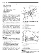
(2) Obtain correct Fuel Line Pressure Test Adapter
Tool Hose. Tool number 6539 is used for 5/16” fuel
lines and tool number 6631 is used for 3/8” fuel lines.
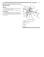
(3) Connect
correct
Fuel
Line
Pressure
Test
Adapter Tool Hose between disconnected fuel line
and fuel rail (Fig. 8).
(4) Connect the 0-414 kPa (0-60 psi) fuel pressure
test gauge (from Gauge Set 5069) to the test port on
the appropriate Adaptor Tool. The DRB III Scan
Tool along with the PEP module, the 500 psi
pressure transducer, and the transducer-to-test
port adapter may also be used in place of the
fuel pressure gauge.
The fittings on both tools must be in good
condition and free from any small leaks before
performing the proceeding test.
(5) Start engine and bring to normal operating
temperature.
(6) Observe test gauge. Normal operating pressure
should be 339 kPa
6
34 kPa (49.2 psi
6
5 psi).
(7) Shut engine off.
(8) Pressure should not fall below 30 psi for five
minutes.
(9) If pressure falls below 30 psi, it must be deter-
mined if a fuel injector, the check valve within the
fuel pump module, or a fuel tube/line is leaking.
(10) Again, start engine and bring to normal oper-
ating temperature.
(11) Shut engine off.
(12) Testing for fuel injector or fuel rail leak-
age: Clamp off the rubber hose portion of Adaptor
Tool between the fuel rail and the test port “T” on
Adapter Tool. If pressure now holds at or above 30
psi, a fuel injector or the fuel rail is leaking.
(13) Testing for fuel pump check valve, filter/
regulator check valve or fuel tube/line leakage:
Clamp off the rubber hose portion of Adaptor Tool
between the vehicle fuel line and test port “T” on
Adapter Tool. If pressure now holds at or above 30
psi, a leak may be found at a fuel tube/line. If no
leaks are found at fuel tubes or lines, one of the
check valves in either the electric fuel pump or filter/
regulator may be leaking.
Note: A quick loss of pressure usually indicates a
defective check valve in the filter/regulator. A slow
loss of pressure usually indicates a defective check
valve in the electric fuel pump.
The electric fuel pump is not serviced separately.
Replace the fuel pump module assembly. The filter/
regulator may be replaced separately on certain
applications. Refer to Fuel Filter/Fuel Pressure Reg-
ulator Removal/Installation for additional informa-
tion.
FUEL PUMP AMPERAGE TEST
This amperage (current draw) test is to be done in
conjunction with the Fuel Pump Pressure Test, Fuel
Pump Capacity Test and Fuel Pressure Leak Down
Test. Before performing the amperage test, be sure
the temperature of the fuel tank is above 50° F (10°
C).
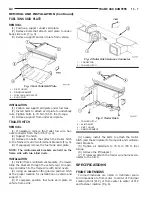
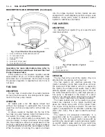
The DRB Scan Tool along with the DRB Low Cur-
rent Shunt (LCS) adapter (Fig. 9) and its test leads
will be used to check fuel pump amperage specifica-
tions.
(1) Be sure fuel tank contains fuel before starting
test. If tank is empty or near empty, amperage read-
ings will be incorrect.
(2) Obtain LCS adapter.
(3) Plug cable from LCS adapter into DRB scan
tool at SET 1 receptacle.
(4) Plug DRB into vehicle 16–way connector (data
link connector).
(5) Connect (-) and (+) test cable leads into LCS
adapter receptacles. Use 10 amp (10A +) receptacle
and common (-) receptacles.
(6) Gain access to MAIN MENU on DRB screen.
(7) Press DVOM button on DRB.
Fig. 8 Connecting Adapter Tool—Typical
1 – VEHICLE FUEL LINE
2 – TEST PORT “T”
3 – SPECIAL TOOL 6923, 6631, 6541 OR 6539
4 – FUEL PRESSURE TEST GAUGE
5 – FUEL LINE CONNECTION AT RAIL
6 – FUEL RAIL
14 - 8
FUEL SYSTEM
XJ
DIAGNOSIS AND TESTING (Continued)
Summary of Contents for Cherokee 2000
Page 4: ......
Page 36: ......
Page 96: ...Fig 105 Gear Tooth Contact Patterns 3 60 TUBE 181 AND 186 FBI AXLE XJ ADJUSTMENTS Continued...
Page 100: ...Installer D 144 Installer W 262 3 64 TUBE 181 AND 186 FBI AXLE XJ SPECIAL TOOLS Continued...
Page 134: ...Fig 79 Gear Tooth Contact Patterns 3 98 194 RBI AXLE XJ ADJUSTMENTS Continued...
Page 166: ...Fig 59 Gear Tooth Contact Patterns 3 130 8 1 4 REAR AXLE XJ ADJUSTMENTS Continued...
Page 215: ...Fig 8 Clutch Components And Inspection XJ CLUTCH 6 5 DIAGNOSIS AND TESTING Continued...
Page 226: ......
Page 231: ...Fig 8 Clutch Components And Inspection XJ CLUTCH 6 5 DIAGNOSIS AND TESTING Continued...
Page 242: ......
Page 284: ......
Page 300: ......
Page 372: ......
Page 376: ......
Page 382: ......
Page 404: ......
Page 412: ......
Page 416: ......
Page 430: ......
Page 444: ......
Page 448: ......
Page 468: ......
Page 482: ......
Page 500: ......
Page 508: ......
Page 520: ......
Page 526: ......
Page 532: ......
Page 540: ......
Page 550: ......
Page 647: ...Fig 16 2 5L Engine XJ 8W 90 CONNECTOR LOCATIONS 8W 90 23 DESCRIPTION AND OPERATION Continued...
Page 648: ...Fig 17 4 0L Engine 8W 90 24 8W 90 CONNECTOR LOCATIONS XJ DESCRIPTION AND OPERATION Continued...
Page 649: ...Fig 18 4 0L Engine XJ 8W 90 CONNECTOR LOCATIONS 8W 90 25 DESCRIPTION AND OPERATION Continued...
Page 662: ...Fig 31 Liftgate 8W 90 38 8W 90 CONNECTOR LOCATIONS XJ DESCRIPTION AND OPERATION Continued...
Page 666: ......
Page 810: ......
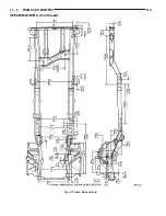
Page 826: ...Fig 6 Frame Dimensions 13 8 FRAME AND BUMPERS XJ SPECIFICATIONS Continued...
Page 828: ......
Page 1316: ......
Page 1328: ......
Page 1353: ...Fig 3 Hood Components XJ BODY 23 25 REMOVAL AND INSTALLATION Continued...
Page 1396: ...WELD LOCATIONS UPPER COWL 23 68 BODY XJ SPECIFICATIONS Continued...
Page 1397: ...UPPER COWL XJ BODY 23 69 SPECIFICATIONS Continued...
Page 1398: ...COWL 23 70 BODY XJ SPECIFICATIONS Continued...
Page 1399: ...A PILLAR XJ BODY 23 71 SPECIFICATIONS Continued...
Page 1400: ...A PILLAR 23 72 BODY XJ SPECIFICATIONS Continued...
Page 1401: ...A PILLAR XJ BODY 23 73 SPECIFICATIONS Continued...
Page 1402: ...A PILLAR 23 74 BODY XJ SPECIFICATIONS Continued...
Page 1403: ...B PILLAR XJ BODY 23 75 SPECIFICATIONS Continued...
Page 1404: ...D PILLAR 23 76 BODY XJ SPECIFICATIONS Continued...
Page 1405: ...FUEL FILLER OPENING XJ BODY 23 77 SPECIFICATIONS Continued...
Page 1406: ...CARGO AREA FLOOR PAN 23 78 BODY XJ SPECIFICATIONS Continued...
Page 1407: ...ROOF AND D PILLAR XJ BODY 23 79 SPECIFICATIONS Continued...
Page 1408: ...LIFTGATE OPENING 23 80 BODY XJ SPECIFICATIONS Continued...
Page 1409: ...ROOF XJ BODY 23 81 SPECIFICATIONS Continued...
Page 1410: ...ROOF 23 82 BODY XJ SPECIFICATIONS Continued...
Page 1411: ...FRAME RAIL XJ BODY 23 83 SPECIFICATIONS Continued...
Page 1412: ...FRAME RAIL 23 84 BODY XJ SPECIFICATIONS Continued...
Page 1413: ...FRAME RAIL XJ BODY 23 85 SPECIFICATIONS Continued...
Page 1414: ...FRAME RAIL 23 86 BODY XJ SPECIFICATIONS Continued...
Page 1415: ...REINFORCEMENT XJ BODY 23 87 SPECIFICATIONS Continued...
Page 1416: ...FRONT INNER FENDER 23 88 BODY XJ SPECIFICATIONS Continued...
Page 1417: ...FRONT INNER FENDER AND RADIATOR CLOSURE PANEL XJ BODY 23 89 SPECIFICATIONS Continued...
Page 1418: ...REINFORCEMENT 23 90 BODY XJ SPECIFICATIONS Continued...
Page 1419: ...FRONT FENDER XJ BODY 23 91 SPECIFICATIONS Continued...
Page 1420: ...BODY SIDE 23 92 BODY XJ SPECIFICATIONS Continued...
Page 1421: ...REAR WHEELHOUSE XJ BODY 23 93 SPECIFICATIONS Continued...
Page 1422: ...REAR INNER WHEELHOUSE 23 94 BODY XJ SPECIFICATIONS Continued...
Page 1423: ...BODY SIDE XJ BODY 23 95 SPECIFICATIONS Continued...
Page 1424: ...BODY SIDE 23 96 BODY XJ SPECIFICATIONS Continued...
Page 1425: ...BODY SIDE XJ BODY 23 97 SPECIFICATIONS Continued...
Page 1426: ...BODY SIDE 23 98 BODY XJ SPECIFICATIONS Continued...
Page 1427: ...BODY SIDE XJ BODY 23 99 SPECIFICATIONS Continued...
Page 1428: ...BODY SIDE 23 100 BODY XJ SPECIFICATIONS Continued...
Page 1429: ...UNDERBODY XJ BODY 23 101 SPECIFICATIONS Continued...
Page 1430: ...UNDERBODY 23 102 BODY XJ SPECIFICATIONS Continued...
Page 1431: ...UNDERBODY XJ BODY 23 103 SPECIFICATIONS Continued...
Page 1432: ...UNDERBODY 23 104 BODY XJ SPECIFICATIONS Continued...
Page 1433: ...UNDERBODY XJ BODY 23 105 SPECIFICATIONS Continued...
Page 1434: ...UNDERBODY 23 106 BODY XJ SPECIFICATIONS Continued...
Page 1435: ...UNDERBODY XJ BODY 23 107 SPECIFICATIONS Continued...
Page 1436: ...UNDERBODY 23 108 BODY XJ SPECIFICATIONS Continued...
Page 1437: ...UNDERBODY XJ BODY 23 109 SPECIFICATIONS Continued...
Page 1438: ...UNDERBODY 23 110 BODY XJ SPECIFICATIONS Continued...
Page 1439: ...UNDERBODY XJ BODY 23 111 SPECIFICATIONS Continued...
Page 1440: ...BODY SEALING LOCATIONS APPLICATION METHODS 23 112 BODY XJ SPECIFICATIONS Continued...
Page 1441: ...COWL AND DASH PANEL XJ BODY 23 113 SPECIFICATIONS Continued...
Page 1442: ...DASH PANEL AND FLOOR PAN 23 114 BODY XJ SPECIFICATIONS Continued...
Page 1443: ...FLOOR PAN XJ BODY 23 115 SPECIFICATIONS Continued...
Page 1444: ...REAR INNER WHEELHOUSE 23 116 BODY XJ SPECIFICATIONS Continued...
Page 1445: ...FRONT INNER WHEELHOUSE XJ BODY 23 117 SPECIFICATIONS Continued...
Page 1446: ...BODY SIDE 23 118 BODY XJ SPECIFICATIONS Continued...
Page 1447: ...BODY SIDE XJ BODY 23 119 SPECIFICATIONS Continued...
Page 1448: ...BODY SIDE 23 120 BODY XJ SPECIFICATIONS Continued...
Page 1449: ...ROOF PANEL XJ BODY 23 121 SPECIFICATIONS Continued...
Page 1450: ...FUEL FILLER HOUSING 23 122 BODY XJ SPECIFICATIONS Continued...
Page 1451: ...LIFTGATE OPENING XJ BODY 23 123 SPECIFICATIONS Continued...
Page 1452: ...STRUCTURAL ADHESIVE LOCATIONS LEFT QUARTER PANEL 23 124 BODY XJ SPECIFICATIONS Continued...
Page 1453: ...REAR WHEELHOUSE XJ BODY 23 125 SPECIFICATIONS Continued...
Page 1454: ...ROOF BOWS 23 126 BODY XJ SPECIFICATIONS Continued...
Page 1464: ......
Page 1512: ......
Page 1528: ......


