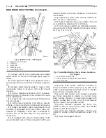
INTAKE MANIFOLD AIR TEMPERATURE
SENSOR—PCM INPUT
DESCRIPTION
The 2–wire Intake Manifold Air Temperature (IAT)
sensor is installed in the intake manifold with the
sensor element extending into the air stream.
The IAT sensor is a two-wire Negative Thermal
Coefficient (NTC) sensor. Meaning, as intake mani-
fold temperature increases, resistance (voltage) in the
sensor decreases. As temperature decreases, resis-
tance (voltage) in the sensor increases.
OPERATION
The IAT sensor provides an input voltage to the
Powertrain Control Module (PCM) indicating the
density of the air entering the intake manifold based
upon intake manifold temperature. At key-on, a
5–volt power circuit is supplied to the sensor from
the PCM. The sensor is grounded at the PCM
through a low-noise, sensor-return circuit.
The PCM uses this input to calculate the following:
•
Injector pulse-width
•
Adjustment of spark timing (to help prevent
spark knock with high intake manifold air-charge
temperatures)
The resistance values of the IAT sensor is the same
as for the Engine Coolant Temperature (ECT) sensor.
MANIFOLD ABSOLUTE PRESSURE (MAP)
SENSOR—PCM INPUT
DESCRIPTION
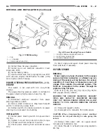
The Manifold Absolute Pressure (MAP) sensor is
attached to the side of the engine throttle body with
2 screws. The sensor is connected to the throttle body
with a rubber L-shaped fitting.
OPERATION
The MAP sensor is used as an input to the Power-
train Control Module (PCM). It contains a silicon
based sensing unit to provide data on the manifold
vacuum that draws the air/fuel mixture into the com-
bustion chamber. The PCM requires this information
to determine injector pulse width and spark advance.
When manifold absolute pressure (MAP) equals
Barometric pressure, the pulse width will be at max-
imum.
A 5 volt reference is supplied from the PCM and
returns a voltage signal to the PCM that reflects
manifold pressure. The zero pressure reading is 0.5V
and full scale is 4.5V. For a pressure swing of 0–15
psi, the voltage changes 4.0V. To operate the sensor,
it is supplied a regulated 4.8 to 5.1 volts. Ground is
provided through the low-noise, sensor return circuit
at the PCM.
The MAP sensor input is the number one contrib-
utor to fuel injector pulse width. The most important
function of the MAP sensor is to determine baromet-
ric pressure. The PCM needs to know if the vehicle is
at sea level or at a higher altitude, because the air
density changes with altitude. It will also help to cor-
rect for varying barometric pressure. Barometric
pressure and altitude have a direct inverse correla-
tion; as altitude goes up, barometric goes down. At
key-on, the PCM powers up and looks at MAP volt-
age, and based upon the voltage it sees, it knows the
current barometric pressure (relative to altitude).
Once the engine starts, the PCM looks at the voltage
again, continuously every 12 milliseconds, and com-
pares the current voltage to what it was at key-on.
The difference between current voltage and what it
was at key-on, is manifold vacuum.
During key-on (engine not running) the sensor
reads (updates) barometric pressure. A normal range
can be obtained by monitoring a known good sensor.
As the altitude increases, the air becomes thinner
(less oxygen). If a vehicle is started and driven to a
very different altitude than where it was at key-on,
the barometric pressure needs to be updated. Any
time the PCM sees Wide Open Throttle (WOT), based
upon Throttle Position Sensor (TPS) angle and RPM,
it will update barometric pressure in the MAP mem-
ory cell. With periodic updates, the PCM can make
its calculations more effectively.
The PCM uses the MAP sensor input to aid in cal-
culating the following:
•
Manifold pressure
•
Barometric pressure
•
Engine load
•
Injector pulse-width
•
Spark-advance programs
•
Shift-point strategies (certain automatic trans-
missions only)
•
Idle speed
•
Decel fuel shutoff
The MAP sensor signal is provided from a single
piezoresistive element located in the center of a dia-
phragm. The element and diaphragm are both made
of silicone. As manifold pressure changes, the dia-
phragm moves causing the element to deflect, which
stresses the silicone. When silicone is exposed to
stress, its resistance changes. As manifold vacuum
increases, the MAP sensor input voltage decreases
proportionally. The sensor also contains electronics
that condition the signal and provide temperature
compensation.
The PCM recognizes a decrease in manifold pres-
sure by monitoring a decrease in voltage from the
reading stored in the barometric pressure memory
cell. The MAP sensor is a linear sensor; meaning as
pressure changes, voltage changes proportionately.
14 - 32
FUEL SYSTEM
XJ
DESCRIPTION AND OPERATION (Continued)
Summary of Contents for Cherokee 2000
Page 4: ......
Page 36: ......
Page 96: ...Fig 105 Gear Tooth Contact Patterns 3 60 TUBE 181 AND 186 FBI AXLE XJ ADJUSTMENTS Continued...
Page 100: ...Installer D 144 Installer W 262 3 64 TUBE 181 AND 186 FBI AXLE XJ SPECIAL TOOLS Continued...
Page 134: ...Fig 79 Gear Tooth Contact Patterns 3 98 194 RBI AXLE XJ ADJUSTMENTS Continued...
Page 166: ...Fig 59 Gear Tooth Contact Patterns 3 130 8 1 4 REAR AXLE XJ ADJUSTMENTS Continued...
Page 215: ...Fig 8 Clutch Components And Inspection XJ CLUTCH 6 5 DIAGNOSIS AND TESTING Continued...
Page 226: ......
Page 231: ...Fig 8 Clutch Components And Inspection XJ CLUTCH 6 5 DIAGNOSIS AND TESTING Continued...
Page 242: ......
Page 284: ......
Page 300: ......
Page 372: ......
Page 376: ......
Page 382: ......
Page 404: ......
Page 412: ......
Page 416: ......
Page 430: ......
Page 444: ......
Page 448: ......
Page 468: ......
Page 482: ......
Page 500: ......
Page 508: ......
Page 520: ......
Page 526: ......
Page 532: ......
Page 540: ......
Page 550: ......
Page 647: ...Fig 16 2 5L Engine XJ 8W 90 CONNECTOR LOCATIONS 8W 90 23 DESCRIPTION AND OPERATION Continued...
Page 648: ...Fig 17 4 0L Engine 8W 90 24 8W 90 CONNECTOR LOCATIONS XJ DESCRIPTION AND OPERATION Continued...
Page 649: ...Fig 18 4 0L Engine XJ 8W 90 CONNECTOR LOCATIONS 8W 90 25 DESCRIPTION AND OPERATION Continued...
Page 662: ...Fig 31 Liftgate 8W 90 38 8W 90 CONNECTOR LOCATIONS XJ DESCRIPTION AND OPERATION Continued...
Page 666: ......
Page 810: ......
Page 826: ...Fig 6 Frame Dimensions 13 8 FRAME AND BUMPERS XJ SPECIFICATIONS Continued...
Page 828: ......
Page 1316: ......
Page 1328: ......
Page 1353: ...Fig 3 Hood Components XJ BODY 23 25 REMOVAL AND INSTALLATION Continued...
Page 1396: ...WELD LOCATIONS UPPER COWL 23 68 BODY XJ SPECIFICATIONS Continued...
Page 1397: ...UPPER COWL XJ BODY 23 69 SPECIFICATIONS Continued...
Page 1398: ...COWL 23 70 BODY XJ SPECIFICATIONS Continued...
Page 1399: ...A PILLAR XJ BODY 23 71 SPECIFICATIONS Continued...
Page 1400: ...A PILLAR 23 72 BODY XJ SPECIFICATIONS Continued...
Page 1401: ...A PILLAR XJ BODY 23 73 SPECIFICATIONS Continued...
Page 1402: ...A PILLAR 23 74 BODY XJ SPECIFICATIONS Continued...
Page 1403: ...B PILLAR XJ BODY 23 75 SPECIFICATIONS Continued...
Page 1404: ...D PILLAR 23 76 BODY XJ SPECIFICATIONS Continued...
Page 1405: ...FUEL FILLER OPENING XJ BODY 23 77 SPECIFICATIONS Continued...
Page 1406: ...CARGO AREA FLOOR PAN 23 78 BODY XJ SPECIFICATIONS Continued...
Page 1407: ...ROOF AND D PILLAR XJ BODY 23 79 SPECIFICATIONS Continued...
Page 1408: ...LIFTGATE OPENING 23 80 BODY XJ SPECIFICATIONS Continued...
Page 1409: ...ROOF XJ BODY 23 81 SPECIFICATIONS Continued...
Page 1410: ...ROOF 23 82 BODY XJ SPECIFICATIONS Continued...
Page 1411: ...FRAME RAIL XJ BODY 23 83 SPECIFICATIONS Continued...
Page 1412: ...FRAME RAIL 23 84 BODY XJ SPECIFICATIONS Continued...
Page 1413: ...FRAME RAIL XJ BODY 23 85 SPECIFICATIONS Continued...
Page 1414: ...FRAME RAIL 23 86 BODY XJ SPECIFICATIONS Continued...
Page 1415: ...REINFORCEMENT XJ BODY 23 87 SPECIFICATIONS Continued...
Page 1416: ...FRONT INNER FENDER 23 88 BODY XJ SPECIFICATIONS Continued...
Page 1417: ...FRONT INNER FENDER AND RADIATOR CLOSURE PANEL XJ BODY 23 89 SPECIFICATIONS Continued...
Page 1418: ...REINFORCEMENT 23 90 BODY XJ SPECIFICATIONS Continued...
Page 1419: ...FRONT FENDER XJ BODY 23 91 SPECIFICATIONS Continued...
Page 1420: ...BODY SIDE 23 92 BODY XJ SPECIFICATIONS Continued...
Page 1421: ...REAR WHEELHOUSE XJ BODY 23 93 SPECIFICATIONS Continued...
Page 1422: ...REAR INNER WHEELHOUSE 23 94 BODY XJ SPECIFICATIONS Continued...
Page 1423: ...BODY SIDE XJ BODY 23 95 SPECIFICATIONS Continued...
Page 1424: ...BODY SIDE 23 96 BODY XJ SPECIFICATIONS Continued...
Page 1425: ...BODY SIDE XJ BODY 23 97 SPECIFICATIONS Continued...
Page 1426: ...BODY SIDE 23 98 BODY XJ SPECIFICATIONS Continued...
Page 1427: ...BODY SIDE XJ BODY 23 99 SPECIFICATIONS Continued...
Page 1428: ...BODY SIDE 23 100 BODY XJ SPECIFICATIONS Continued...
Page 1429: ...UNDERBODY XJ BODY 23 101 SPECIFICATIONS Continued...
Page 1430: ...UNDERBODY 23 102 BODY XJ SPECIFICATIONS Continued...
Page 1431: ...UNDERBODY XJ BODY 23 103 SPECIFICATIONS Continued...
Page 1432: ...UNDERBODY 23 104 BODY XJ SPECIFICATIONS Continued...
Page 1433: ...UNDERBODY XJ BODY 23 105 SPECIFICATIONS Continued...
Page 1434: ...UNDERBODY 23 106 BODY XJ SPECIFICATIONS Continued...
Page 1435: ...UNDERBODY XJ BODY 23 107 SPECIFICATIONS Continued...
Page 1436: ...UNDERBODY 23 108 BODY XJ SPECIFICATIONS Continued...
Page 1437: ...UNDERBODY XJ BODY 23 109 SPECIFICATIONS Continued...
Page 1438: ...UNDERBODY 23 110 BODY XJ SPECIFICATIONS Continued...
Page 1439: ...UNDERBODY XJ BODY 23 111 SPECIFICATIONS Continued...
Page 1440: ...BODY SEALING LOCATIONS APPLICATION METHODS 23 112 BODY XJ SPECIFICATIONS Continued...
Page 1441: ...COWL AND DASH PANEL XJ BODY 23 113 SPECIFICATIONS Continued...
Page 1442: ...DASH PANEL AND FLOOR PAN 23 114 BODY XJ SPECIFICATIONS Continued...
Page 1443: ...FLOOR PAN XJ BODY 23 115 SPECIFICATIONS Continued...
Page 1444: ...REAR INNER WHEELHOUSE 23 116 BODY XJ SPECIFICATIONS Continued...
Page 1445: ...FRONT INNER WHEELHOUSE XJ BODY 23 117 SPECIFICATIONS Continued...
Page 1446: ...BODY SIDE 23 118 BODY XJ SPECIFICATIONS Continued...
Page 1447: ...BODY SIDE XJ BODY 23 119 SPECIFICATIONS Continued...
Page 1448: ...BODY SIDE 23 120 BODY XJ SPECIFICATIONS Continued...
Page 1449: ...ROOF PANEL XJ BODY 23 121 SPECIFICATIONS Continued...
Page 1450: ...FUEL FILLER HOUSING 23 122 BODY XJ SPECIFICATIONS Continued...
Page 1451: ...LIFTGATE OPENING XJ BODY 23 123 SPECIFICATIONS Continued...
Page 1452: ...STRUCTURAL ADHESIVE LOCATIONS LEFT QUARTER PANEL 23 124 BODY XJ SPECIFICATIONS Continued...
Page 1453: ...REAR WHEELHOUSE XJ BODY 23 125 SPECIFICATIONS Continued...
Page 1454: ...ROOF BOWS 23 126 BODY XJ SPECIFICATIONS Continued...
Page 1464: ......
Page 1512: ......
Page 1528: ......


