


ELECTROSTATIC DISCHARGE (ESD) SENSITIVE
DEVICES
All ESD sensitive components are solid state and a
symbol (Fig. 2) is used to indicate this. When han-
dling any component with this symbol comply with
the following procedures to reduce the possibility of
electrostatic charge build up on the body and inad-
vertent discharge into the component. If it is not
known whether the part is ESD sensitive, assume
that it is.
(1) Always touch a known good ground before han-
dling the part. This should be repeated while han-
dling the part and more frequently after sliding
across a seat, sitting down from a standing position,
or walking a distance.
(2) Avoid touching electrical terminals of the part,
unless instructed to do so by a written procedure.
(3) When using a voltmeter, be sure to connect the
ground lead first.
(4) Do not remove the part from its protective
packing until it is time to install the part.
(5) Before removing the part from its package,
ground the package to a known good ground on the
vehicle.
DIAGNOSIS AND TESTING
TROUBLESHOOTING TOOLS
When diagnosing a problem in an electrical circuit
there are several common tools necessary. These tools
are listed and explained below.
•
Jumper Wire - This is a test wire used to con-
nect two points of a circuit. It can be used to bypass
an open in a circuit.
WARNING: NEVER USE A JUMPER WIRE ACROSS
A
LOAD,
SUCH
AS
A
MOTOR,
CONNECTED
BETWEEN A BATTERY FEED AND GROUND.
•
Voltmeter - Used to check for voltage on a cir-
cuit. Always connect the black lead to a known good
ground and the red lead to the positive side of the
circuit.
CAUTION: Most of the electrical components used
in today’s vehicle are solid state. When checking
voltages in these circuits use a meter with a 10-me-
gohm or greater impedance rating.
•
Ohmmeter
-
Used
to
check
the
resistance
between two points of a circuit. Low or no resistance
in a circuit means good continuity.
CAUTION: - Most of the electrical components used
in today’s vehicle are Solid State. When checking
resistance in these circuits use a meter with a
10-megohm or greater impedance rating. In addi-
tion, make sure the power is disconnected from the
circuit. Circuits that are powered up by the vehicle
electrical system can cause damage to the equip-
ment and provide false readings.
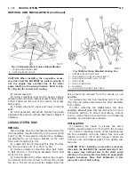
•
Probing Tools - These tools are used for probing
terminals in connectors (Fig. 3). Select the proper
size tool from Special Tool Package 6807, and insert
it into the terminal being tested. Use the other end
of the tool to insert the meter probe.
INTERMITTENT AND POOR CONNECTIONS
Most intermittent electrical problems are caused
by faulty electrical connections or wiring. It is also
possible for a sticking component or relay to cause a
problem. Before condemning a component or wiring
assembly check the following items.
•
Connectors are fully seated
•
Spread terminals, or terminal push out
•
Terminals in the wiring assembly are fully
seated into the connector/component and locked in
position
•
Dirt or corrosion on the terminals. Any amount
of corrosion or dirt could cause an intermittent prob-
lem
•
Damaged connector/component casing exposing
the item to dirt and moisture
•
Wire insulation that has rubbed through causing
a short to ground
•
Some or all of the wiring strands broken inside
of the insulation covering.
•
Wiring broken inside of the insulation
Fig. 2 Electrostatic Discharge Symbol
Fig. 3 Probing Tool
1 – SPECIAL TOOL 6801
2 – PROBING END
8W - 01 - 8
8W - 01 GENERAL INFORMATION
XJ
DESCRIPTION AND OPERATION (Continued)
Summary of Contents for Cherokee 2000
Page 4: ......
Page 36: ......
Page 96: ...Fig 105 Gear Tooth Contact Patterns 3 60 TUBE 181 AND 186 FBI AXLE XJ ADJUSTMENTS Continued...
Page 100: ...Installer D 144 Installer W 262 3 64 TUBE 181 AND 186 FBI AXLE XJ SPECIAL TOOLS Continued...
Page 134: ...Fig 79 Gear Tooth Contact Patterns 3 98 194 RBI AXLE XJ ADJUSTMENTS Continued...
Page 166: ...Fig 59 Gear Tooth Contact Patterns 3 130 8 1 4 REAR AXLE XJ ADJUSTMENTS Continued...
Page 215: ...Fig 8 Clutch Components And Inspection XJ CLUTCH 6 5 DIAGNOSIS AND TESTING Continued...
Page 226: ......
Page 231: ...Fig 8 Clutch Components And Inspection XJ CLUTCH 6 5 DIAGNOSIS AND TESTING Continued...
Page 242: ......
Page 284: ......
Page 300: ......
Page 372: ......
Page 376: ......
Page 382: ......
Page 404: ......
Page 412: ......
Page 416: ......
Page 430: ......
Page 444: ......
Page 448: ......
Page 468: ......
Page 482: ......
Page 500: ......
Page 508: ......
Page 520: ......
Page 526: ......
Page 532: ......
Page 540: ......
Page 550: ......
Page 647: ...Fig 16 2 5L Engine XJ 8W 90 CONNECTOR LOCATIONS 8W 90 23 DESCRIPTION AND OPERATION Continued...
Page 648: ...Fig 17 4 0L Engine 8W 90 24 8W 90 CONNECTOR LOCATIONS XJ DESCRIPTION AND OPERATION Continued...
Page 649: ...Fig 18 4 0L Engine XJ 8W 90 CONNECTOR LOCATIONS 8W 90 25 DESCRIPTION AND OPERATION Continued...
Page 662: ...Fig 31 Liftgate 8W 90 38 8W 90 CONNECTOR LOCATIONS XJ DESCRIPTION AND OPERATION Continued...
Page 666: ......
Page 810: ......
Page 826: ...Fig 6 Frame Dimensions 13 8 FRAME AND BUMPERS XJ SPECIFICATIONS Continued...
Page 828: ......
Page 1316: ......
Page 1328: ......
Page 1353: ...Fig 3 Hood Components XJ BODY 23 25 REMOVAL AND INSTALLATION Continued...
Page 1396: ...WELD LOCATIONS UPPER COWL 23 68 BODY XJ SPECIFICATIONS Continued...
Page 1397: ...UPPER COWL XJ BODY 23 69 SPECIFICATIONS Continued...
Page 1398: ...COWL 23 70 BODY XJ SPECIFICATIONS Continued...
Page 1399: ...A PILLAR XJ BODY 23 71 SPECIFICATIONS Continued...
Page 1400: ...A PILLAR 23 72 BODY XJ SPECIFICATIONS Continued...
Page 1401: ...A PILLAR XJ BODY 23 73 SPECIFICATIONS Continued...
Page 1402: ...A PILLAR 23 74 BODY XJ SPECIFICATIONS Continued...
Page 1403: ...B PILLAR XJ BODY 23 75 SPECIFICATIONS Continued...
Page 1404: ...D PILLAR 23 76 BODY XJ SPECIFICATIONS Continued...
Page 1405: ...FUEL FILLER OPENING XJ BODY 23 77 SPECIFICATIONS Continued...
Page 1406: ...CARGO AREA FLOOR PAN 23 78 BODY XJ SPECIFICATIONS Continued...
Page 1407: ...ROOF AND D PILLAR XJ BODY 23 79 SPECIFICATIONS Continued...
Page 1408: ...LIFTGATE OPENING 23 80 BODY XJ SPECIFICATIONS Continued...
Page 1409: ...ROOF XJ BODY 23 81 SPECIFICATIONS Continued...
Page 1410: ...ROOF 23 82 BODY XJ SPECIFICATIONS Continued...
Page 1411: ...FRAME RAIL XJ BODY 23 83 SPECIFICATIONS Continued...
Page 1412: ...FRAME RAIL 23 84 BODY XJ SPECIFICATIONS Continued...
Page 1413: ...FRAME RAIL XJ BODY 23 85 SPECIFICATIONS Continued...
Page 1414: ...FRAME RAIL 23 86 BODY XJ SPECIFICATIONS Continued...
Page 1415: ...REINFORCEMENT XJ BODY 23 87 SPECIFICATIONS Continued...
Page 1416: ...FRONT INNER FENDER 23 88 BODY XJ SPECIFICATIONS Continued...
Page 1417: ...FRONT INNER FENDER AND RADIATOR CLOSURE PANEL XJ BODY 23 89 SPECIFICATIONS Continued...
Page 1418: ...REINFORCEMENT 23 90 BODY XJ SPECIFICATIONS Continued...
Page 1419: ...FRONT FENDER XJ BODY 23 91 SPECIFICATIONS Continued...
Page 1420: ...BODY SIDE 23 92 BODY XJ SPECIFICATIONS Continued...
Page 1421: ...REAR WHEELHOUSE XJ BODY 23 93 SPECIFICATIONS Continued...
Page 1422: ...REAR INNER WHEELHOUSE 23 94 BODY XJ SPECIFICATIONS Continued...
Page 1423: ...BODY SIDE XJ BODY 23 95 SPECIFICATIONS Continued...
Page 1424: ...BODY SIDE 23 96 BODY XJ SPECIFICATIONS Continued...
Page 1425: ...BODY SIDE XJ BODY 23 97 SPECIFICATIONS Continued...
Page 1426: ...BODY SIDE 23 98 BODY XJ SPECIFICATIONS Continued...
Page 1427: ...BODY SIDE XJ BODY 23 99 SPECIFICATIONS Continued...
Page 1428: ...BODY SIDE 23 100 BODY XJ SPECIFICATIONS Continued...
Page 1429: ...UNDERBODY XJ BODY 23 101 SPECIFICATIONS Continued...
Page 1430: ...UNDERBODY 23 102 BODY XJ SPECIFICATIONS Continued...
Page 1431: ...UNDERBODY XJ BODY 23 103 SPECIFICATIONS Continued...
Page 1432: ...UNDERBODY 23 104 BODY XJ SPECIFICATIONS Continued...
Page 1433: ...UNDERBODY XJ BODY 23 105 SPECIFICATIONS Continued...
Page 1434: ...UNDERBODY 23 106 BODY XJ SPECIFICATIONS Continued...
Page 1435: ...UNDERBODY XJ BODY 23 107 SPECIFICATIONS Continued...
Page 1436: ...UNDERBODY 23 108 BODY XJ SPECIFICATIONS Continued...
Page 1437: ...UNDERBODY XJ BODY 23 109 SPECIFICATIONS Continued...
Page 1438: ...UNDERBODY 23 110 BODY XJ SPECIFICATIONS Continued...
Page 1439: ...UNDERBODY XJ BODY 23 111 SPECIFICATIONS Continued...
Page 1440: ...BODY SEALING LOCATIONS APPLICATION METHODS 23 112 BODY XJ SPECIFICATIONS Continued...
Page 1441: ...COWL AND DASH PANEL XJ BODY 23 113 SPECIFICATIONS Continued...
Page 1442: ...DASH PANEL AND FLOOR PAN 23 114 BODY XJ SPECIFICATIONS Continued...
Page 1443: ...FLOOR PAN XJ BODY 23 115 SPECIFICATIONS Continued...
Page 1444: ...REAR INNER WHEELHOUSE 23 116 BODY XJ SPECIFICATIONS Continued...
Page 1445: ...FRONT INNER WHEELHOUSE XJ BODY 23 117 SPECIFICATIONS Continued...
Page 1446: ...BODY SIDE 23 118 BODY XJ SPECIFICATIONS Continued...
Page 1447: ...BODY SIDE XJ BODY 23 119 SPECIFICATIONS Continued...
Page 1448: ...BODY SIDE 23 120 BODY XJ SPECIFICATIONS Continued...
Page 1449: ...ROOF PANEL XJ BODY 23 121 SPECIFICATIONS Continued...
Page 1450: ...FUEL FILLER HOUSING 23 122 BODY XJ SPECIFICATIONS Continued...
Page 1451: ...LIFTGATE OPENING XJ BODY 23 123 SPECIFICATIONS Continued...
Page 1452: ...STRUCTURAL ADHESIVE LOCATIONS LEFT QUARTER PANEL 23 124 BODY XJ SPECIFICATIONS Continued...
Page 1453: ...REAR WHEELHOUSE XJ BODY 23 125 SPECIFICATIONS Continued...
Page 1454: ...ROOF BOWS 23 126 BODY XJ SPECIFICATIONS Continued...
Page 1464: ......
Page 1512: ......
Page 1528: ......


