-49-
Set this parameter to 0 if the motor has no oscillation. Increase the value properly only when the
motor has obvious oscillation. The larger the value is, the better the oscillation suppression result will be.
When the oscillation suppression function is enabled, the rated motor current and no-load current
must be correct. Otherwise, the V/F oscillation suppression effect will not be satisfactory.
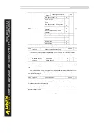
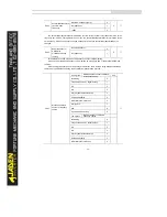
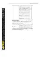
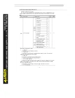
P2.13
Voltage source for
V/Fseparation
Digital setting(P2.14)
0
0
☆
AI1
1
AI2
2
AI3( keyboard potentiometer)
3
Pulse setting(DI5)
4
Multi-reference
5
Simple PLC
6
PID
7
Communication
8
100.0% corresponding to motorrated voltage(P1.02)
P2.14
Voltage digital setting for V/F
separation
0V~ motorrated voltage
0V
☆
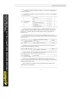
V/F separation is generally applicable to scenarios such as induction heating, inverse power supply
and motor torque control.
If V/F separated control is enabled, the output voltage can be set in P2.14 or by means of analog,
multi-reference, simple PLC, PID or communication. If you set the output voltage by means of non-digital
setting, 100% of the setting corresponds to the motor rated voltage. If a negative percentage is set, its
absolute value is used as the effective value.
•
0: Digital setting (P2.14)
The output voltage is set directly in P2.14.
•
1: AI1; 2: AI2; 3: AI3
The output voltage is set by AI terminals.
•
4: Pulse setting (DI5)
The output voltage is set by pulses of the terminal D
丨
5.
Pulse setting specification: voltage range 9-30 V, frequency range 0-100 kHz
•
5: Multi-reference
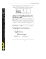
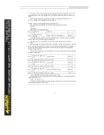
If the voltage source is multi-reference, parameters in group P4 and PC must be set to determine the
corresponding relationship between setting signal and setting voltage. 100.0% of the multi-reference
setting in group PC corresponds to the rated motor voltage.
Summary of Contents for DLB1-0D40S2G
Page 11: ...11 Graph 1 722 30KW product outline dimensions Graph 1 837 55KW product outline dimensions...
Page 12: ...12 Graph 1 875 110KW product outline dimensions Graph 1 9 132 160KW product outline dimensions...
Page 14: ...14 2 Wirings 2 1 Standard wiring diagrams Graph 2 8 0 4 18 5KW inverter wiring diagram...
Page 15: ...15 Graph 2 922 400KW inverter wiring diagram...
Page 159: ...159...

