-138-
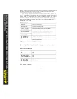
Note:
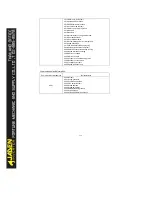
Communication setting value is relevant perc entage value, 10000 corresponding to
100.00%, -10000 corresponding-100.00%. For frequency data, this percentage is relevant
to maximum frequency(P0.10); torque data is percentage to P3.10(torque upper limit).
Command input:(write only)
Command address
Command function
2000
0001:FWD operation
0002:REV operation
0003:FWD JOG
0004:REVJOG
0005:Coast to stop
0006:Decelerate to stop
0007:Fault reset
Read inverter status:(read only)
Statusaddress
Statusfunction
3000
0001:FWD operation
0002:REV operation
0003:stop
Parameter lock verification:(Return value 8888H means parameter lock passed)
Passord address
Input password
1F00
*****
Digital output control:(write only)
Command address
Command content
2001
BIT0:DO1 output control
BIT1:DO2 output control
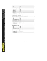
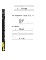
101A
Accumulative power-on time
101B
Accumulative running time
101C
Input pulse frequency, unit1Hz
101D
Communication setting value
101E
Encoder feedback speed
101F
Main frequency X
1020
Auxiliary frequency Y
Summary of Contents for DLB1-0D40S2G
Page 11: ...11 Graph 1 722 30KW product outline dimensions Graph 1 837 55KW product outline dimensions...
Page 12: ...12 Graph 1 875 110KW product outline dimensions Graph 1 9 132 160KW product outline dimensions...
Page 14: ...14 2 Wirings 2 1 Standard wiring diagrams Graph 2 8 0 4 18 5KW inverter wiring diagram...
Page 15: ...15 Graph 2 922 400KW inverter wiring diagram...
Page 159: ...159...

