-39-
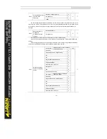
P0.25
Acceleration/Decelera
tion time base
frequency
Maximum frequency(P0.10)
0
0
★
Set frequency
1
100Hz
2
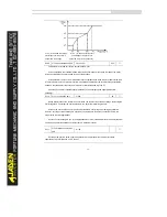
The acceleration/deceleration time indicates the time for the Inverter to increase from 0 Hz to the
frequency set in P0.25. If this parameter is set to 1, the acceleration/deceleration time is related to the
set frequency. If the set frequency changes frequently, the motor's acceleration/deceleration also
changes.
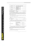
P0.26
Base frequency for
UP/DOW N
modification during
running
Running frequency
0
0
★
Set frequency
1
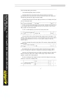
This parameter is valid only when the frequency source is digital setting.
It is used to set the base frequency to be modified by using keys and or theterminal UP/DOW N
function.
If the running frequency and set frequency are different, there will be a large difference between
the Inverter's performances during the acceleration/ deceleration process.
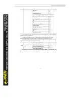
P0.27
Binding command
source to frequency
source
One’s place
Binding operation panel command
to frequency source
000
☆
No binding
0
Frequency source by digital setting
1
AI1
2
AI2
3
AI3( keyboard potentiometer)
4
Pulse setting(DI5)
5
Multi-reference instruction
6
Simple PLC
7
PID
8
Communication setting
9
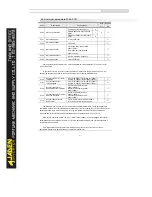
Ten’s place
Binding terminal command to
frequency source
No binding
0
Frequency source by digital setting
1
AI1
2
AI2
3
AI3( keyboard potentiometer)
4
Pulse setting(DI5)
5
Multi-reference instruction
6
Summary of Contents for DLB1-0D40S2G
Page 11: ...11 Graph 1 722 30KW product outline dimensions Graph 1 837 55KW product outline dimensions...
Page 12: ...12 Graph 1 875 110KW product outline dimensions Graph 1 9 132 160KW product outline dimensions...
Page 14: ...14 2 Wirings 2 1 Standard wiring diagrams Graph 2 8 0 4 18 5KW inverter wiring diagram...
Page 15: ...15 Graph 2 922 400KW inverter wiring diagram...
Page 159: ...159...


