-162-
Appendix IIIBrake accessories
The motor and load's regenerative energy is almost completely consumed on the braking
resistor when braking.
In theory, the power of the braking resistor is consistent with the braking power. But in
consideration that the de-rating is 70%, you can calculate the power of the braking resistor
according to the formula 0.7 x Pr = Pb x D.
•
Pr refers to the power of resistor.
•
D refers to the braking frequency (percentage of the regenerative process to the whole
working process)
«
Note: brake unit and brake resistor must be used together.
For DLB1 series inverters, models under 15KW are with internal brake units and user shall
select external brake units for models over 18.5KW.
You can select different resistance and power based on actual needs. However, the
resistance must not be lower than the recommended value. The power may be higher than the
recommended value.
The braking resistor model is dependent on the generation power of the motor in the actual
system and is also related to the system inertia, deceleration time and potential energy load.
For systems with high inertia, and/or rapid deceleration times, or frequent braking sequences,
the braking resistor with higher power and lower resistance value should be selected.
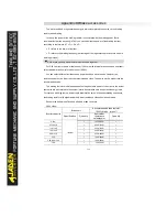
Recommended value of brake units and brake resistors
380V class:
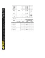
Inverter capacity
Brake unit
Recommended brake resistor
(
100% brake torque
)
Specification
Quantity
Equivalent
resistance
value/power
Quantity
0.75G
Internal
1
1800Ω/60W
1
0.75P/1.1G
1
900Ω/100W
1
1.1G/1.5P
1
600Ω/150W
1
1.5G/2.2P
1
400Ω/260W
1
2.2G/3.7P
1
250Ω/260W
1
3.7G
1
150Ω/390W
1
5.5G/5.5P/7.5P
1
100Ω/520W
1
7.5G
1
75Ω/780W
1
Summary of Contents for DLB1-0D40S2G
Page 11: ...11 Graph 1 722 30KW product outline dimensions Graph 1 837 55KW product outline dimensions...
Page 12: ...12 Graph 1 875 110KW product outline dimensions Graph 1 9 132 160KW product outline dimensions...
Page 14: ...14 2 Wirings 2 1 Standard wiring diagrams Graph 2 8 0 4 18 5KW inverter wiring diagram...
Page 15: ...15 Graph 2 922 400KW inverter wiring diagram...
Page 159: ...159...


