-91-
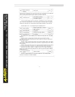
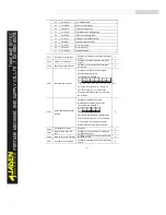
P8.47
Module temperature
threshold
0.00
℃
~100
℃
75
℃
☆
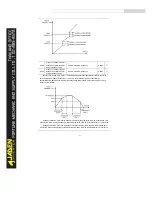
When the heatsink temperature of the Inverter reaches the value of this parameter, the corresponding
DO becomes ON, indicating that the module temperature reaches the threshold.
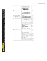
P8.48
Cooling fan control
Fan working during running
0
0
☆
Fan working continously
1
It is used to set the working mode of the cooling fan. If this parameter is set to 0, the fan works
when the Inverter is in running state. When the Inverter stops, the cooling fan works if the heatsink
temperature is higher than 40°C, and stops working if the heatsink temperature is lower than 40°C.
If this parameter is set to 1, the cooling fan keeps working after power-on.
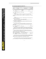
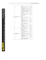
P8.49
Wakeup frequency
Dormant frequency(P8.51)~ maximum
frequency(P0.10)
0.00Hz
☆
P8.50
Wakeup delay time
0.0s~6500.0s
0.0s
☆
P8.51
Dormant frequency
0.00Hz~wakeup frequency(P8.49)
0.00Hz
☆
P8.52
Dormant delay time
0.0s~6500.0s
0.0s
☆
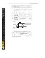
These parameters are used to implement the dormant and wakeup functions in the water supply
application.
When the Inverter is in running state, the Inverter enters the dormant state and stops
automatically after the dormant delay time (P8.52) if the set frequency is lower than or equal to the
dormant frequency (P8.51).
When the Inverter is in dormant state and the current running command is effective, the Inverters
starts up after the wakeup delay time (P8.50) if the set frequency is higher than or equal to the wakeup
frequency (P8.49).
Generally, set the wakeup frequency equal to or higher than the dormant frequency. If the wakeup
frequency and dormant frequency are set to 0, the dormant and wakeup functions are disabled.
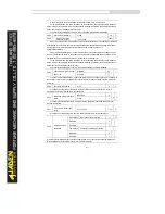
When the dormant function is enabled, if the frequency source is PID, whether PID operation is
performed in the dormant state is determined by PA.28. In this case, select PID operation enabled in
the stop state (FA-28 = 1).
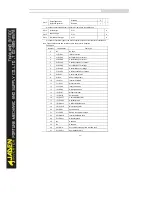
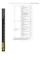
P8.53
Current running time
reached
0.0Min~6500.0Min
0.0Min
☆
When the output power (d0.05) is not equal to the required value, you can perform linear
correction on output power by using this parameter.
Summary of Contents for DLB1-0D40S2G
Page 11: ...11 Graph 1 722 30KW product outline dimensions Graph 1 837 55KW product outline dimensions...
Page 12: ...12 Graph 1 875 110KW product outline dimensions Graph 1 9 132 160KW product outline dimensions...
Page 14: ...14 2 Wirings 2 1 Standard wiring diagrams Graph 2 8 0 4 18 5KW inverter wiring diagram...
Page 15: ...15 Graph 2 922 400KW inverter wiring diagram...
Page 159: ...159...


