-46-
4.4
V/F control parameters:P2.00-P2.15
Group P2 is valid only for V/F control.
The V/F control mode is applicable to low load applications (fan or pump) or applications where one
Inverter operates multiple motors or there is a large difference between the Inverter power and the motor
power.
Code
Description
Setting range
Defa
ult
Restri
ctions
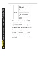
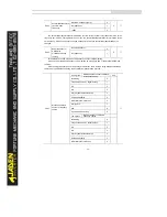
P2.00
V/F curve setting
One’s
place
Ten’s
place
Linear V/F
0
0
☆
Multi-point V/F
1
Square V/F
2
1.2 time V/F
3
1.4 time V/F
4
1.5 time V/F
5
1.6 time V/F
6
1.7 time V/F
7
1.8 time V/F
8
Reserved
9
VF complete separation
mode
10
VF half separation mode
11
Hundr
ed’s
place
No automatic voltage
regulation function
0
Have automatic voltage
regulation function
1
Have automatic voltage
regulation function, but not
during decelerations.
2
One’s place, Ten’s place:V/F mode
•
0: Linear V/F
It is applicable to common constant torque load.
•
1: Multi-point V/F
It is applicable to special load such as dehydrator and centrifuge. Any such V/F curve can be
obtained by setting parameters of P2.03 to P2.08.
•
2: Square V/F
It is applicable to centrifugal loads such as fan and pump.
•
3 to 8: V/F curve between linear V/F and square V/F
•
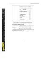
10: V/F complete separation
In this mode, the output frequency and output voltage of the Inverter are independent. The output
frequency is determined by the frequency source, and the output voltage is determined by "Voltage
source for V/F separation" (P2.13).
It is applicable to induction heating, inverse power supply and torque motor control.
•
11: V/F half separation
Summary of Contents for DLB1-0D40S2G
Page 11: ...11 Graph 1 722 30KW product outline dimensions Graph 1 837 55KW product outline dimensions...
Page 12: ...12 Graph 1 875 110KW product outline dimensions Graph 1 9 132 160KW product outline dimensions...
Page 14: ...14 2 Wirings 2 1 Standard wiring diagrams Graph 2 8 0 4 18 5KW inverter wiring diagram...
Page 15: ...15 Graph 2 922 400KW inverter wiring diagram...
Page 159: ...159...


