-81-
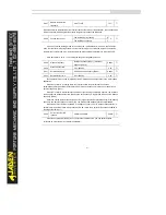
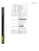
P7.06
Load speed display
coefficient
0.0001~6.5000
1.000
0
☆
This parameter is used to adjust the relationship between the output frequency of the Inverter and
the load speed. For details, see the description of P7.12.
P7.07
Heatsink temperature of
inverter module
0.0
℃
~100.0
℃
12
℃
●
It is used to display the insulated gate bipolar transistor (IGBT) temperature of the inverter
module, and the IGBT overheat protection value of the inverter module depends on the model.
P7.08
Rectification module
temperature
0.0
℃
~100.0
℃
0
℃
●
P7.09
Accumulativerunning time
0h~65535h
0h
●
It is used to display the accumulative running time of the Inverter. After the accumulative running
time reaches the value set in P8.17, the terminal with the digital output function 12 becomes ON.
P7.10
Product number
Inverter Product number
-
●
P7.11
Software version
Software version of control board
-
●
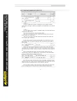
P7.12
Number of decimal places for
load speed display
0decimal place
0
1
☆
1decimal place
1
2decimal place
2
3decimal place
3
P7.12 is used to set the number of decimal places for load speed display. The following gives an
example to explain how to calculate the load speed:
Assume that P7.06 (Load speed display coefficient) is 2.000 and P7.12 is 2 (2 decimal places).
When the running frequency of the Inverter is 40.00 Hz, the load speed is 40.00 x 2.000 = 80.00
(display of 2 decimal places).
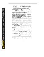
If the Inverter is in the stop state, the load speed is the speed corresponding to the set frequency,
namely, "set load speed". If the set frequency is 50.00 Hz, the load speed in the stop state is 50.00 x
2.000 = 100.00 (display of 2 decimal places).
P7.13
Accumulativepower-on time
0h~65535h
-
●
It is used to display the accumulative power-on time of the Inverter since the delivery. If the time
reaches the set power-on time (P8.17), the terminal with the digital output function 24 becomes ON.
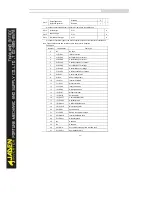
P7.14
Accumulativepower
consumption
0~65535 kWh
-
●
It is used to display the accumulative power consumption of the Inverter until now.
Summary of Contents for DLB1-0D40S2G
Page 11: ...11 Graph 1 722 30KW product outline dimensions Graph 1 837 55KW product outline dimensions...
Page 12: ...12 Graph 1 875 110KW product outline dimensions Graph 1 9 132 160KW product outline dimensions...
Page 14: ...14 2 Wirings 2 1 Standard wiring diagrams Graph 2 8 0 4 18 5KW inverter wiring diagram...
Page 15: ...15 Graph 2 922 400KW inverter wiring diagram...
Page 159: ...159...


