-27-
4 Function codes (Parameters)
Legends
:
“★”
:this parameter’s setting value is not editable when inverter is at operation status;
“●”
:this parameter’s value is observed value, not editable;
“☆”
:this parameter’s setting value is editable when inverter is at stop or operation status;
“▲”
:this parameter is “factory parameter” not for editing;
“
-”:this parameter is depending on model.
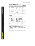
4.1 Basicmonitoring parameters:d0.00-d0.41
d0 parameter group is used for monitoring inverter operation status. User can read by
panel display or by communications for remote controls. d0.00~d0.31are defined by
P7.03&P7.04foroperation & stop monitor parameters.
Function code
Name
Unit
d0.00
Running frequency(Hz)
0.01Hz
Inverter absolute value of theoretical running frequency.
d0.01
Set frequency(Hz)
0.01Hz
Inverter absolute value of theoretical set frequency.
d0.02
DC Bus voltage(V)
0.1V
DC bus voltage; detectedvalue.
d0.03
Output voltage(V)
1V
Inverterrunning state output voltage.
d0.04
Output current(A)
0.01A
Motorrunning state output current.
d0.05
Output power(kW)
0.1kW
Motorrunning state output power.
d0.06
Output torque(%)
0.1%
Motorrunning state output torque percentage.
d0.07
DI input status
1
This displays the current state of DI terminals. After the value is converted into a binary number, each
bit corresponds to a DI. "1" indicates high level signal, and "0" indicates low level signal. The
corresponding relationship between bits and DIs is described in the following table.
Summary of Contents for DLB1-0D40S2G
Page 11: ...11 Graph 1 722 30KW product outline dimensions Graph 1 837 55KW product outline dimensions...
Page 12: ...12 Graph 1 875 110KW product outline dimensions Graph 1 9 132 160KW product outline dimensions...
Page 14: ...14 2 Wirings 2 1 Standard wiring diagrams Graph 2 8 0 4 18 5KW inverter wiring diagram...
Page 15: ...15 Graph 2 922 400KW inverter wiring diagram...
Page 159: ...159...


