altered: 18.05.2017
additional manual
J3 C
+
J3C S
actuators
with Positioner (DPS)
technical changes reserved
Dat.: 10 08 14 0
compiled:
03.02.2017
Name:
AB
Electrical alignment
For the adjustment drive you have to wire and switch on the power supply at plug 1.
Note: At actuators with DPS and BSR you have to unplug the BSR Accupack from the
circuit board before you start the adjustment drive!
1.
switch off power supply and open the cover
2.
put DIP-switches in neutral position (see fig. 1)
3.
put DIP-switch 1 to position
„on “(see fig. 2)
4.
switch on the power supply
5.
put DIP-switch 1 back to neutral position
6.
now the actuator drives in both end positions
After the adjustment drive the actuator drives to the position according to your input
signal. The adjustment is finished.
Manuel alignment (
J3 S
+
J3C S
)
1.
switch off power supply and open the cover
2.
release plug 3 from terminal 3 (Positioning signal)
3.
make a bypass on terminal 3 between Pin 1 and Ground
4.
switch on the power supply
5.
release the bypass
6.
now the actuator drives in both end positions
After the adjustment drive the actuator drives to the position according to your input signal
Configuration of signal
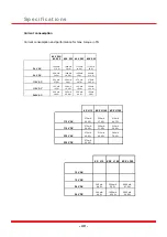
The signals mode could be configurate by DIP-switches. Plug off the external power and positioner plugs and easily configurated
those switches as seen in the image below.
Adjust working angel
For change the working angel of the positioner system you have to adjust first the motor stop cam (position “open” or “close”). Please
note if you want to use the position confirmation of the voltfree contacts (plug 4) , you have to adjust the cams for it too, after you
adjust the motor stop cams. For adjust the cams you can get more information at our main manual,
chapter “adjust the cams”. After
the adjustment of the cams you have to adjust the positioner system too.
fig. 2
fig. 1


