background image

P o s i t i o n   A d j u s t m e n t

- 22 -

Safety

Preparatory measures

Note

However, the cable lead that needs to be restored for the assembly.

All bolts and gaskets are to set to its original position for the assembly. Please note the instructions of 
the valve manufacturers and system operators.

All work in the actuator must be carried out only by qualified personnel and disconnected power 
source. Touching live components can have a dangerous electrical shock and damage the 
electronics!

Purpose

The actuators are pre-adjusted. Depending on the envisaged use, clearance or lack of alignment 
of valve connections or adapters it may be necessary to adjust the actuator in his travels to the 
particular valve or to adjust feedback different due to the circuit. After prolonged use or under 
strong vibrations, readjustment may be required.

1.

Pull the connector after loosening the screws (note seals) .

2

.

Loosen the screws on the hand wheel and remove it, respectively remove the T-handle gently
pull   upwards with a wide-edge screwdriver.

3.

Loosen and remove the housing screws.

4.

Carefully pull cover straight up and do not twist, possibly for type 140 and 300 push the upper
part with both hands up (levering with a screwdriver can lead to leaks). Put the cover to one side 
(cables can stay connected to the board). 

Summary of Contents for J2 L/H 10

Page 1: ...for J J Quarter Turn Actuators Manual Manual Manual Te l 4 9 5 1 8 1 6 0 1 7 i n f o j u j d e u t s c h l a n d d e w w w j u j d e u t s c h l a n d d e...

Page 2: ...ny J J Deutschland GmbH neither amended multiplied nor transmitted for use to third party To the demand of these documents please address J J Deutschland GmbH This documentation may not be extended wi...

Page 3: ...10 and 20 18 Conversion double square adapter 19 Electrical Installation 20 Position Adjustment 22 Jumper Configuration 26 FAQ s 27 Special models Actuators with BSR Battery Spring Return 29 Actuators...

Page 4: ...ty indications The actuators are designed for the automation of industrial valves e g ball valves and butterfly valves divergent applications requires a consultation by the manufacturer The operationa...

Page 5: ...t carry the actuator on the hand wheel and do not attach any hoists to the hand wheel Entry control Check directly after delivery the actuator for possible damages in transit and faults Don t leave an...

Page 6: ...to synchronize the transmission then exit the adjustment path manually and turn back to the starting position Then switch from MAN to AUTO and move the handlever hand wheel onesmore Switch off all equ...

Page 7: ...ons switch To clean the housing do not use abrasive corrosive or flammable cleaners or high pressure cleaning equipment Settings and Commissioning Make sure that the starting or the test settings on t...

Page 8: ...connection is via DIN connector The type label and the wiring diagram to make every actuator easily identifiable Equipment J3 S20 J3C S20 bis 85 24 240 V AC DC 50 60Hz J2 L10 J3C L140 300 24 V AC DC...

Page 9: ...rque Break torque Voltage range Protection J3C S85 J3C L H 140 Torque Break torque Voltage range L Voltage range H Protection Torque Break torque Voltage range L Voltage range H Protection J3C L H 300...

Page 10: ...Automatic to Manual AUTO MAN and Wheel and Lever Indicator ptical Position Indicator Dome LED not for model 10 B Optical Position Indicator 0 Hand lever Position Indicator Model J2 J3 Dome Position I...

Page 11: ...the coltage variant L or H and the output torque Nm 2 Type pecifying the series pecifying pecifying emperature range in pecifying the potential to build up to ISO 5211 flange versions tested next to...

Page 12: ...easily trackable 14 Working angle 15 Duty rating M Quality control It is 14 QR Code Production data pecifying the model 2 Type pecifying the series pecifying pecifying emperature range in pecifying th...

Page 13: ...via DPS signal STOP 200 msec 1111 1111 1111 1111 blue Actuator moving via DPS signal to position OPEN 200 msec 1111 1111 1111 1111 blue green Actuator moving via DPS signal to position CLOSE 200 msec...

Page 14: ...y approached Open or Closed Upon actuation of the limit switch the motor is activated again If the motor is running you can switch the lever from MAN toAUTO and the actuator is ready for operation 2 T...

Page 15: ...e active i e the supply voltage must be applied continuously Cabling and connector seals should be checked for proper fit and tightness In cold or hot liquids above or below the temperature range 20 C...

Page 16: ...gon and adaption is at least Insertion size of the specified Should this not be considered it may cause a malfunction or even damage of the actuator depth double squares If possible use headless screw...

Page 17: ...tor on valve bracket and adapter a bracket adapter with screws 8 8 washers 4 nuts screws alternatively with headless screws headless screws 8 12 nuts 12 spring washer 0 Direct mounting Assembling with...

Page 18: ...st be rebuilt with model 10 and 20 if necessary Remodeling of the plate is as follows 1 Undo the screws 2 Screw two threaded pins screws into the flange plate until they press the plate out of the hou...

Page 19: ...4 mm Working steps are as follow Remove the multi flange plate Remove the adapter Insert appropriate adapter Insert the multi flange plate again Model 55 300 Remove the clamp ring Remove the adapter I...

Page 20: ...ors are secured to the actuator with a screw Cable diameter model min max min max 10 85 5mm 5mm 8mm 10 5mm 140 300 8mm 10 5mm small plug large plug Type C industrial standard Type A DIN EN 175301 803A...

Page 21: ...ed off and they are not under pressure or strain Do not route the control cables in parallel to other cables that lead to large electricity consumers Strong electromagnetic fields could induce current...

Page 22: ...clearance or lack of alignment of valve connections or adapters it may be necessary to adjust the actuator in his travels to the particular valve or to adjust feedback different due to the circuit Aft...

Page 23: ...replace the screws and tighten them crosswise Then put on and fixed the handlever or the hand whee Once the electrical connections have been made and the actuator has been switched from AUTO to MAN by...

Page 24: ...to counterclockwise direction cams 1 and 3 The cam 3 should press the lever of the micro switch earlier than the cam 1 approximately 3 To adjust the close position to more than 90 Turn the wrench to...

Page 25: ...direction cams 1 and 3 The cam 3 should press the lever of the micro switch earlier than the cam 1 approximately 3 To adjust the close position at more than 0 Turn the wrench to counterclockwise direc...

Page 26: ...Jumper Configuration Heater active Optional Configuration Heater inactive 26 Basic configuration...

Page 27: ...se completely Actuator is twisted mounted or the end position adjustment is wrong with the valve match The release cams have to be readjusted and or the actuator is to set up correctly The limit switc...

Page 28: ...Special Models Series J3 J3C...

Page 29: ...safe Again energized the actuator moves to the position selected by the switch position of the system wiring diagram The batteries have a long lifetime but it depends on the operating conditions A sta...

Page 30: ...echarge 5 2 1 Configuration security option NO NC Jumper on position SELDIR with jumper NC closed without jumper NO open Battery charge 40mA h Working operation with battery 2 4mA 3 3mA 7 1mA 15 1mA 2...

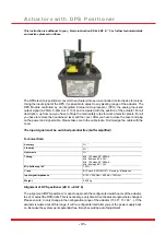
Page 31: ...t maybe could be out of adjustment Alignment of DPS positioner J3 S J3C S This instruction is additional to your Basic instruction J3 S J3C S For further technical details and advices please mind thos...

Page 32: ...the motor stop cam position open or close Please note if you want to use the position confirmation of the voltfree contacts plug 4 you have to adjust the cams for it too after you adjust the motor sto...

Page 33: ...1111 blue green flashing power supply on actuator moving to closed 100 1111 1111 1111 1111 blue red flashing OPEN control signal OPEN actuator moving to OPEN CLOSE control signal CLOSE actuator movin...

Page 34: ...the actuator drives in the same position like before reason after the adjustment of the cams you have to adjust the DPS system too help see chapter adjust the DPS positioner systems The angel position...

Page 35: ...maximum value The minimum and maximum value can not be shown caused by the design It is simply a sector The ohmic values can vary from actuator to actuator for the same position Each actuator is indiv...

Page 36: ...it switches Stecker Plug 4 extern external 1 3 2 L L L Eingang Input Ausgang Output 180 0 Stecker Plug 4 1 3 2 intern internal COM COM Justage of Positions End position The models of J3 J3C Series ele...

Page 37: ...hases continuous NC L N VAC VDC 1 3 2 Stecker Plug 1 Auf Open Zu Close Ansteuerung Control PIN 1 N PIN 2 L Zu Close PIN 1 N PIN 2 3 L Auf Open Stecker Plug 4 1 3 2 Auf Open Zu Close L L L Eingang Inpu...

Page 38: ...A p p e n d i x...

Page 39: ...90kg voltage range S voltage range L voltage range H operating time 90 break torque operating torque duty rating ED protection class temperature range flange double square DIN3337 potentialfree limit...

Page 40: ...370 mA 40 7 W 270 mA 29 5 W 110 V DC 100 mA 14 3 W 200 mA 18 6 W 180 mA 19 6 W 150 mA 16 5 W 240 V AC 200 mA 39 6 W 200 mA 45 9 W 200 mA 48 W 160 mA 38 W J2 H10 J3C H140 J3C H300 110 V AC 272 mA 29 9...

Page 41: ...Wiring Diagrams position of plugs 1 3 4 Models H L 20 35 55 85 POWER 3 4 POS E L S 1 Models H L 140 300 41 Model H L 10 1 4...

Page 42: ...ndlagen potentialfree Stecker Plug 1 L N 1 3 2 Auf Open Zu Close AC DC 3 Draht 2 Punkt Regelung 2 point control DC 2 Draht 2 wires Stecker Plug 4 J2 J3 J3C Standard BSR Ansteuerung PIN 1 N PIN 2 L Clo...

Page 43: ...rnal L N VAC VDC 1 3 2 Stecker Plug 1 StandardAC DC L N VDC 1 3 2 Stecker Plug 1 Alternativ DC Zus tzliche Endschalter Auxiliary limit switches Stecker Plug 4 extern external 1 3 2 L L L Eingang Input...

Page 44: ...3 L 180 Schaltplan f r 3 Positionen Antrieb am Beispiel 0 90 180 Wiring diagram for 3 Position actuator for example 0 90 180 Zus tzliche Endschalter Auxiliary limit switches Stecker Plug 4 extern exte...

Page 45: ...L L Eingang Input Ausgang Output extern external 1 3 2 COM Stecker Plug 4 intern internal COM not available for J2 10 L N VAC VDC 1 3 2 Stecker Plug 1 Auf Open Zu Close Schaltplan f r 2 Phasen Ansteue...

Page 46: ...Dimensional Drawing 4xM6 4xM5 05 36 52 52 6 621 130 51 181 15 7 401 14 46 J2 H L 10...

Page 47: ...Dimensional Drawing 181 130 51 55 55 42 14 11 9 6 3 5 0 110 110 1 1 3 1 5 1 4xM6 4xM5 4xM5 841 47 J3 S20...

Page 48: ...14 11 9 130 51 42 55 55 169 110 15 13 11 4xM6 4xM5 4xM5 0 5 6 3 181 Dimensional Drawing 48 J3C S20 35...

Page 49: ...B MAN A AUTO 110 181 130 51 16 19 55 55 4xM8 4xM6 14 17 5 0 7 0 691 Dimensional Drawing 49 J3C S55...

Page 50: ...16 19 130 51 55 55 691 1 7 6 011 14 17 4xM8 4xM6 0 5 0 7 1 8 1 Dimensional Drawing 50 J3C S85...

Page 51: ...Dimensional Drawing 214 128 107 235 180 90 A AUTO M MAN 25 254 1 0 2 7 0 4xM10 4xM8 17 22 POWER POS E L S 51 J3C H L 140 300...

Page 52: ...Te l 4 9 5 1 8 1 6 0 1 7 i n f o j u j d e u t s c h l a n d d e w w w j u j d e u t s c h l a n d d e...

Page 53: ...have to remove the handwheel lever and the cover After you have to close the cover and plug on the power and signal cable Please take care to the cable route Don t wedge the cable with the cover The I...

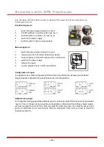
Page 54: ...r supply and open the cover 2 release plug 3 from terminal 3 Positioning signal 3 make a bypass on terminal 3 between Pin 1 and Ground 4 switch on the power supply 5 release the bypass 6 now the actua...

Page 55: ...blue red flashing For further information about status functions consult our Basic instruction J3 S J3C S Status LED DPS board internal Abb 4 OPEN control signal OPEN actuator moving to OPEN CLOSE con...

Page 56: ...adjust the DPS positioner systems The motor cams are adjusted by the user but the actuator drives in the same position like before reason after the adjustment of the cams you have to adjust the DPS sy...

Reviews: