


26
Uni-3 Technical Manual
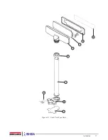
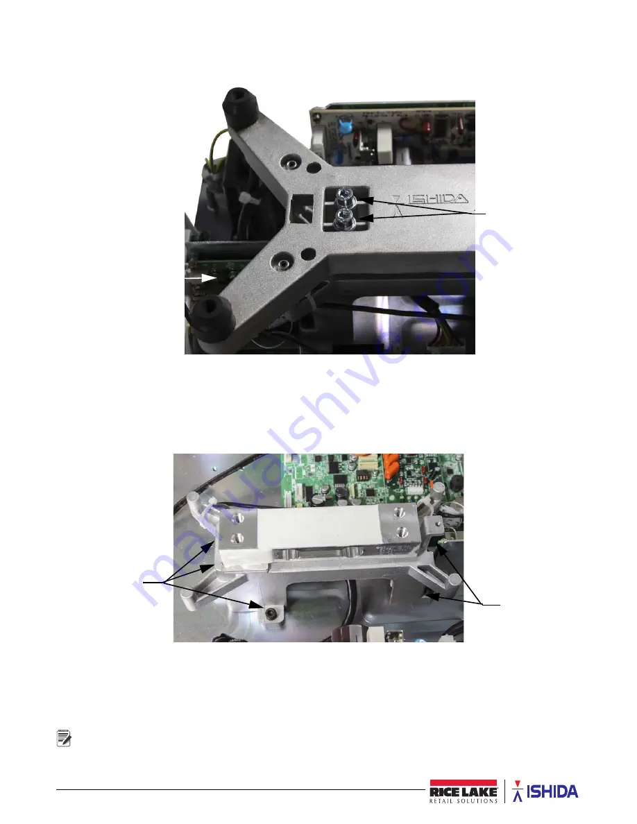
Platter Support and Load Cell Disassembly Procedure
1. Remove the two Allen head hex bolts (5 mm) from the platter support. See Figure 2-10.
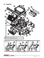
Figure 2-10. Platter Support Disassembly
2. Remove the platter support.
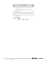
3. Remove the five machine screws securing the printer.
4. Remove the peel sensor, label sensor, motor and print-head ribbon cables.
5. Move the printer to the side.
6. Remove the five Allen head hex bolts (4 mm) securing the load cell bracket. See Figure 2-11.
Figure 2-11. Load Cell Bracket Disassembly
7. Unsolder the five wires from the A/D board (PS-067).
8. Remove the two Allen head hex bolts (5 mm) and remove the load cell and load cell bracket.
9. Carefully turn over the load cell bracket and remove the two Allen head hex bolts (5 mm).
10. Detach the load cell.
Reverse this procedure for assembly.
Hex Bolts
Machine Screws
Hex Bolts
Hex
Note


