


Installation
25
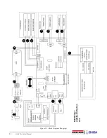
7. Remove the front printer cover. See Figure 2-8.
Figure 2-8. Remove Front Printer Cover
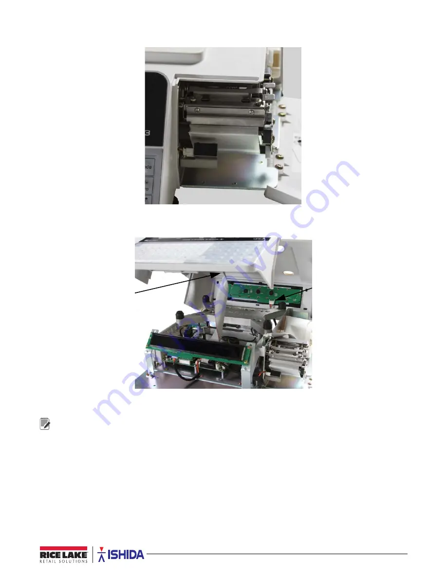
8. Carefully pull the top cover up just enough to unplug the keyboard connector cable and the customer side
display cable (bench models only). See Figure 2-9.
Figure 2-9. Unplug Cables from Top Cover
9. Once unplugged, remove the top cover.
Reverse this procedure for assembly.
Note