background image

91

CLEANING AND CARE

inVENTer Connect controller platform | Operating instructions

•  Indoor humidity/temperature sensor


    Slotted 

screwdriver


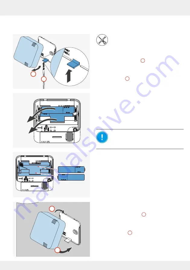
At the bottom, press the latching lever carefully 

upwards with a suitable tool (e.g. screwdriver) until 

the housing disengages (

1

).


Lift the upper hooks of the housing out of the eye-

lets of the base plate and remove the housing from 

the base plate (

2

).


The base plate and housing are separate.


Remove the used batteries from the housing's  

battery compartment and dispose of them properly.

NOTICE:

 Incorrect polarity of the 

batteries.

Insert the batteries according to the polarity 

marked in the housing.


Insert the new batteries into the battery compart-

ment in the housing.


Once the batteries are inserted, the housing can 

be snapped back into the base plate.


Slide the housing from above onto the base plate 

and hook the hooks of the housing back into the 

eyelets of the base plate (

1

).


At the bottom, slide the housing over the locking 

hook and press it gently onto the base plate until it 

clicks into place (

2

).


The batteries have been replaced and the Indoor 

humidity/temperature sensor has been reinstalled.

2

1

CLICK

2

1

-         +

-         +

AAA

Summary of Contents for Connect inner cover

Page 1: ...www inventer eu Operating Instructions inVENTer Connect Controller platform ...

Page 2: ... therefore no guarantee of compliance can be provided This documentation describes the functionality of the standard scope For reasons of clarity the documentation does not purport to cover all details on all types of the product and cannot cover every conceivable scenario for commissioning operation cleaning and care The illustrations in this document may differ slightly from the design of the pr...

Page 3: ...y zone 40 3 8 Acknowledging warnings notifications 44 3 9 Resetting the controller and devices 46 4 Operation and setup with the app 48 4 1 Adding the controller to the app 48 4 2 The screen of the app 50 4 3 Device overview menu 51 4 4 Device identification 53 4 5 Renaming components 53 4 6 Changing the direction of rotation of the fan 54 4 7 Assigning devices to the ventilation zones 55 4 8 Defi...

Page 4: ...ns Direct or possible risk of property damage due to an adverse event state If you see these signs ensure you observe the described measures to prevent possible hazards and or damage Other symbols and notices used in this documentation In addition to the safety instructions the following symbols are used A TIP symbol indicates practical and useful tips for handling the devices on the inVENTer Conn...

Page 5: ...ntilation units with heat recovery Requirements for intended use Use the units integrated into the ventilation system only in accordance with the applications that are described in this documentation and only in conjunction with devices that are recommend ed approved and named by inVENTer GmbH in this documentation Changes or modifications to the devices are not permitted In particular use the FTS...

Page 6: ...not play with the system s devices NOTICE If the locking arm of the inner cover is in the wrong position the locking arm can break off Before the closing flap is re fitted the locking arm must be swivelled to the right This is done exclusively using the Easy Connect e16 controller or the inVENTer Mobile app To do this switch all devices to pause 3 6 Boost Pause or when operating via app 4 2 4 8 Se...

Page 7: ...t The controller also serves as the system interface for the inVENTer Mobile app Android iOS Communication between the mobile device and the controller takes place via Bluetooth Low Energy BLE There are two ways to operate the inVENTer Connect controller platform Directly via the controller Via the inVENTer Mobile app in conjunction with the controller In order to be able to use the full range of ...

Page 8: ...complete the display screen shows the corresponding symbol for the device in question The controller assigns all newly paired devices to ventilation zone 1 by default This can be changed later and different ventilation profiles can be assigned to the ventilation zones 4 Operation and setup via app If the user disconnects a device and thus removes it from the ventilation system the device specific ...

Page 9: ...tion modes with different speed levels in which the respective inVENTer ventilation unit then operates Heat recovery In heat recovery mode each ventilation unit changes direction supply air extract air every 70 seconds Ventilation units can be paired so that two units form a pair that works in opposite phases i e one ventilation unit works in ventilation while the other one vents After 70 seconds ...

Page 10: ...ied value or are within the tolerance range for this value If there are any deviations the newly measured data is transmitted to the controller CS2 Connect CO2 sensor incl humidity temperature sensor Figure 1 CS2 Connect CO2 sensor The CO2 content is a good indicator of the air quality in the room The higher the CO2 content of the air the worse the air quality The CO2 sensor is used for background...

Page 11: ...ored in the ventilation profile factory setting 70 all ventilation units assigned to the ventilation zone are switched to ventilation mode level 3 FTS19 Connect Outdoor humidity temperature sensor Figure 2 FTS19 Connect Outdoor humidity temperature sensor The Outdoor humidity temperature sensor is a radio sensor for measuring the relative humidity and temperature in the ambient air and sending the...

Page 12: ...t e16 controller flashes alternately RED and WHITE The closing flaps on the Connect inner covers remain open or are opened The LED on all Connect inner covers flashes alternately RED and GREEN The LED on the SK19 Connect switching contact flashes alternately RED and GREEN The function remains active until the air pressure drops below the safety relevant limit again Then all of the ventilation unit...

Page 13: ...ucture after a connection is made with the controller Ventilation zone summary To view the status of each zone and make quick settings such as changing the ventilation profile ventilation mode ventilation level activating the boost function etc Device overview The list of devices paired in the system is displayed including their names ventilation zone and status information Advanced settings To ma...

Page 14: ... 6 Front view of the controller programming unit The sensor keys The capacitive sensor keys available on the programming unit can be used to make quick settings for the ventilation system Navigation keys Use these keys to navigate and change values These keys are also used to set the time Mode key This key is used to switch between different user specific settings or to complete settings that have...

Page 15: ...e application app During this time the LED flashes BLUE Performing a reset Press the mode key and hold it down for 10 seconds Then confirm the reset procedure by briefly pressing the key again This will delete all paired devices and reset all settings If the operation is not confirmed the controller automatically returns to the normal ventilation operation specified by the ventilation profile with...

Page 16: ...f the parameters currently set for a ventilation zone e g ventilation profile and or transmitted by sensors They are the starting point for making settings Figure 7 Information displays on the LCD display screen 1 Warning error message detailed description in the app e g filter change necessary 2 Display of the ambient temperature 3 App notification e g CO2 limit value exceeded 4 Display of the in...

Page 17: ...measured values auto matically No further operation on the devices is required settings are made via the controller During initial commissioning a button on the device is used for operation A multi coloured status LED position see 2 2 Inner cover and 2 3 Sensor system shows the status of the respective device by lighting up in different colours The following displays are possible and uniform for a...

Page 18: ...ss 1 Ö After a successful firmware and hardware check the LED lights up WHITE 2 Ö The controller changes to the radio channel setting Selecting the channel for the RF868 MHZ radio connection Requirements Firmware and hardware check successful Ö The controller searches for the best radio channel the LED flashes alternately GREEN and TURQUOISE TIP There are 5 channels available We recommend using th...

Page 19: ...s setting can be skipped by pressing the mode key Setting the time Requirements Setup by means of the controller Firmware and hardware check successful The channel for the RF868 MHZ radio connection is selected Ö The hour setting is active and flashing Press the mode key to confirm the best channel OR Manually select another channel Press the navigation keys up and down arrow key to navigate throu...

Page 20: ...own arrow key Press the select key to confirm the selec tion hours Ö The hours are set Ö The next field for setting minute display becomes active and flashes Press the navigation keys up and down arrow key and set the minutes Press the mode key to complete the time setting and go to the date setting Setting the date Ö The year display is active and flashes ...

Page 21: ...enu flashes making it active Ö The day display is active and flashes Press the navigation keys up and down arrow key until the required day is set Press the select key to confirm the selec tion day Ö The day is set and the next field for setting month display becomes active and flashes Press the navigation keys up and down arrow key until the current month is set Ö The current month is set Press t...

Page 22: ...humidity at the control ler s installation location Up to 16 system components ventilation devices Connect inner covers sensors switching contact can be paired with the Easy Connect e16 controller The controller system can then be set up via the inVENTer Mobile app or on the controller e g setting ventilation profiles We recommend setting it up via the app To download the app ...

Page 23: ... switching contact has been detected and paired While the white LED is flashing approx 5 minutes the first device to be integrated must be activated so that it can be recognised and paired by the controller TIP Activated units are automatically recognised and paired by the controller To pair system components with the Easy Connect e16 controller and thus integrate them into the inVENTer Connect co...

Page 24: ...ver becomes visible and accessible Tool pin Ø 2 mm 50 mm long e g screwdriver Requirements The Connect inner cover is connected to the power supply Push a tool e g a small screwdriver through the hole as shown to operate the button behind it Press the button to activate the Connect inner cover Ö The LED lights up TURQUOISE 1 Press and hold the button again until the LED lights up GREEN approx 3 s ...

Page 25: ...with the activation of further Connect inner covers and their pairing Ö On the controller s display screen the number shown increases with each paired Connect inner cover Mark the paired Connect inner covers consecutive ly After pairing all Connect inner covers the closing flaps must be refitted If other components sensors switching contact are paired to the controller this step can also be perfor...

Page 26: ...e key 1 on the controller Ö The first symbol flashes Press the Boost Pause key on the controller again until the Pause symbol II flashes Press the selection key on the controller to confirm the pause 2 Ö The locking arm swivels to the right Fit the closing flap Hook the lugs of the closing flap into the electronics cover at the bottom 1 Press the spring clip at the top slightly downwards 2 Guide t...

Page 27: ... the sensor FTS19 Connect Inside on the underside of the housing Ö The LED lights up TURQUOISE 1 Press and hold the button again until the LED lights up permanently GREEN approx 3 s Ö The sensor is ready is automatically recognised and paired by the controller LED flashing green 2 Ö On the controller s display screen after successful pairing the displayed number of paired components increases The ...

Page 28: ...ings If not already done the closing flap must be reattached to the inner cover at this point See Page 26 Swivelling the locking arm to the right Start screen System information After all inner covers ventilation units and sensors have been paired with the controller and the pairing of the components has been confirmed the ventilation systems starts with the factory settings i e all ventilation un...

Page 29: ...ntroller switches the view so that the status of ventilation zone 1 is displayed again Requirements Up to a maximum of 4 zones are set up using the app Press the mode key The first defined ventilation zone ventilation zone 1 appears with its profile icon Ö Ventilation zone 1 and the corresponding profile icon are displayed Ö The display screen shows the total number of pos sible ventilation zones ...

Page 30: ...ey to navigate further until the next ventilation zone appears on the display screen Ö The next ventilation zone ventilation zone 4 and the corresponding profile icon are displayed Once the desired ventilation zone is reached Press the select key to confirm the selected ventilation zone here ventilation zone 4 Ö The status incl all relevant measured values of the selected ventilation zone is displ...

Page 31: ...tem Changing the fan settings brief overview Switching between the setting options is done by pressing the select key The values can then be changed using the arrow keys When setting the active symbol flashes in each case Press the mode key to exit the settings menu and return to the display menu The last setting selected last flashing symbol is set as active The selection order is as follows Vent...

Page 32: ...ed the fan power increases Down arrow key The ventilation level is reduced the fan output decreases Once the desired ventilation level is reached Press the selection key to move to the next setting option Your change is active Ö The symbol for ventilation mode operating mode starts to flash OR Press the mode key to exit the Settings menu Your change is active A changed ventilation level is effecti...

Page 33: ...ile flashes from the System Information screen Press the selection key 2 times Press the arrow keys and navigate through the ventilation modes The re spective selectable symbol flashes Once the desired ventilation mode is reached Press the selection key to move to the next setting option Your change is active Ö The icon for the selected ventilation mode appears on the display screen Ö The next sym...

Page 34: ... the respective profile Sensors integrated into the ventilation zone e g CO2 sensor have priority over the values stored in the weekly timer 7 time controlled ventilation profiles are predefined and listed in a profile table Annex Automatic profiles These automatic profiles are not based on schedules With these the comparison of internal and external temperature and humidity data is used to determ...

Page 35: ...igate through the ventilation profiles The respective selectable symbol flashes Once the desired ventilation profile has been reached Press the mode key to exit the Settings menu Your change is active OR Press the selection key to move to the next setting option ventilation level again Your change is active Ö The icon for the selected ventilation profile appears on the display screen Ö The symbol ...

Page 36: ...ilation zone can be found in 3 7 Activating the boost pause function by zone Activating the pause function globally Requirements The System information display screen of any ventilation zone here ventilation zone 1 standard zone is called up Press the Boost Pause key Ö The auto symbol flashes on the display screen Press the Boost Pause key Ö The pause symbol flashes on the display screen Ö At the ...

Page 37: ... pause time is set for all ventilation zones in the system here e g 4 hours Ö The zone status system information for the current ventilation zone appears on the display screen Here it is ventilation zone 1 standard zone Ö Alternating with the zone status the remaining pause time is displayed The set pause time is displayed alternately with the zone status until it expires ...

Page 38: ...ventilation zone here ventilation zone 1 standard zone is called up Press the Boost Pause key Ö The auto symbol flashes on the display screen Press the Boost Pause key Ö On the display screen the pause symbol flashes and at the same time the pause function time setting timer appears Press the Boost Pause key again Ö On the display screen the boost symbol starts flashing Ö At the same time the boos...

Page 39: ...d boost time is set for all ventilation zones of the system here e g 1 hour Ö The zone status system information for the current ventilation zone appears on the display screen Here it is ventilation zone 1 standard zone Ö Alternating with the zone status the remaining boost time is displayed The set boost time is displayed alternately with the zone status until it expires ...

Page 40: ... boost pause function globally Activating the pause function by zone Requirements The System information display screen of any ventilation zone here ventilation zone 1 standard zone is called up Press the mode key until the zone selection window appears on the display screen Ö The zone selection for ventilation zone 1 is shown on the display screen Select the ventilation zone for which the pause f...

Page 41: ...setting the pause time you can choose between 1 2 4 and 8 hours Press the select key to confirm the selected time setting Ö The desired pause time is set for the selected ventilation zone here e g 4 hours Ö The display screen shows the zone status system information for the ventilation zone that is in pause function here ventilation zone 2 Ö Alternating with the zone status the remaining pause tim...

Page 42: ...up Press the mode key until the zone selection window appears on the display screen Ö The zone selection for ventilation zone 1 is shown on the display screen Select the ventilation zone for which the boost function is to be set Press the up arrow key to navigate to the next zone until you reach the desired zone Here it is ventilation zone 2 for example Ö You have selected the zone for which the b...

Page 43: ...setting the boost time you can choose be tween 1 2 4 and 8 hours Press the select key to confirm the se lected time setting Ö The desired boost time is set for the selected ventilation zone here e g 1 hour Ö The display screen shows the zone status system information for the ventilation zone that is in boost function here ventilation zone 2 Ö Alternating with the zone status the remaining boost ti...

Page 44: ...e update failed Limit value for CO2 content of indoor air exceeded F 04 Battery status of the Indoor Outdoor humidity temperature sensors is low 10 Filter change due soon F 05 Switching contact triggered or switching contact is out of operation System cleaning due soon F 06 Filter change required F 07 System must be cleaned Table 5 Error codes Notifications If the system reports a message the mess...

Page 45: ...ontroller only displays F03 once not four times Requirements The warning triangle symbol appears on the controller display screen The LED on the controller flashes RED WHITE alternately Press the select key to display the error code Ö The error code is displayed on the display screen Press the select key again to display more error codes if necessary Ö Error code changes Other errors have occurred...

Page 46: ... Ö The LED flashes RED for approx 10 seconds Press the mode key again within these 10 seconds to confirm the reset proce dure Ö The LED lights up permanently RED 3 Ö The complete start routine then runs as described for commissioning Inner cover Tool pin Ø 2 mm 50 mm long e g screwdriver First of all the closing flap must be removed 3 2 Initial setup Press the button using a small screwdriver and ...

Page 47: ...door humidity temperature sensor Press and hold the button until the LED lights up solid RED 1 Release the button Ö The LED flashes RED for approx 10 seconds 2 During these 10 seconds press the button on the Indoor humidity temperature sensor on the underside of the housing or Outdoor humidity temperature sensor in the housing or CO2 sensor or Switching contact again to confirm the reset procedure...

Page 48: ...e inVENTer Mobile app icon on the display screen of your mobile device Ö The start screen appears Touch the START button Ö A window appears with a selection of devices that can be paired with your mobile device if necessary Select the Easy Connect e16 button here The most convenient way to operate the inVENTer Connect system is with the inVENTer Mobile app This is why mainly this form of operation...

Page 49: ...de key on the controller until the LED turns BLUE then release it Ö The LED on the controller flashes BLUE and the Bluetooth connection can be established While the LED on the controller is flashing BLUE press the Connect button on your mobile device Ö The controller and mobile device connect Ö A message appears when the connection is completed Press Complete setup Ö A new window opens CONGRATULAT...

Page 50: ...nced settings All settings can be made in a menu The navigation bar contains cross zone control and information options Auto symbol Automatic operation according to the ventila tion profile setting Pause symbol Quick selection of pause for the system Boost symbol Quick selection of boost for the system Switch symbol Quick selection of ON OFF for the system Message symbol System notifications Warni...

Page 51: ...e 1 The devices are displayed in the order in which they were paired and are designated device 1 device 2 device 3 etc This numbering corresponds to the numbering stuck on them during the pairing process and makes allocation easier The following informations are displayed for each device Device name initially Device this can be changed later Device symbol Device status Availability Easy Connect e1...

Page 52: ...r humidity temperature sensor The following displays are possible in the Availability area Green colour a component is integrated in the system and active Yellow colour a connected component is not accessible due to an error Other symbols Symbol Meaning Strength of the radio signal currently present Radio signal weak It is recommended to use a signal amplifier repeater 4 10 for the paired device D...

Page 53: ...reconnect the device 4 5 Renaming components Requirements You are in the Device overview menu The component is identified if necessary 4 4 Press the symbol of the component you want to rename Ö The adjacent window opens The software version and the strength of the radio signal are displayed Press the Edit device name button to edit the device name 26 C 26 Device 5 25 4 C 22 1 20 4 C 44 1 CO2 Devic...

Page 54: ...irectional ventilation mode The selected fan then takes on a different role e g supply air instead of extract air The system automatically ensures that a balance is main tained between supply and extract air Easy Connect e16 Device name Device 1 Software version 5 23 0 Radio signal Edit device name Ventilation device rotation direction V 26 C 26 Device 5 25 4 C 22 1 20 4 C 44 1 CO2 Device 0 Fan 1 ...

Page 55: ...one 1 or the one already assigned different from 1 Ö A selection window opens in which the 4 ventilation zones are displayed Press the ventilation zone to be assigned to the selected device Ö The newly assigned ventilation zone is displayed in the device overview here ventilation zone 4 as an example Scroll through the displayed device overview and continue to assign or change the ventilation zone...

Page 56: ...time to change settings for the ventilation zones Ö The Ventilation zone overview menu opens Press the tile of the ventilation zone A dot indicates that only one ventilation zone has been defined so far 26 C 26 Device 5 25 4 C 22 1 20 4 C 44 1 CO2 Device 0 Fan 1 Device 2 Device 3 Device 6 Ventilation zone 1 Ventilation zone 1 Ventilation zone 1 Ventilation zone 1 Ventilation zone 4 Ventilation zon...

Page 57: ...de control Then press Save Limit recommendations are Pettenkofer 1000 ppm General minimum requirement 1500 ppm Name of the ventilation zone If desired enter a new name for the selected ventilation zone This is freely selectable and can consist of a maximum of 16 characters Press OK and confirm the new name Default Current ventilator power level 1 Ventilation zone 1 Override 25 8 C 24 9 Default Cur...

Page 58: ...profiles appears Press a ventilation profile to select it Ö The window for ventilation zone 1 appears to which another ventilation profile is now assigned Default Current ventilator power level 1 Ventilation zone 1 Override 25 8 C 24 9 Ventilation zone1 Default Default Bedroom Children s room Bathroom Living room Bathroom Living room Kitchen Holiday mode Cellar ventilation without heat recovery Ce...

Page 59: ...lation mode operating mode and where you can change these settings by overriding them Default Current ventilator power level 1 Ventilation zone 1 Override 25 8 C 24 9 Easy Connect e16 Ventilation zone 1 Ventilation zone overview 25 8 C 24 9 Easy Connect e16 Ventilation zone 2 Ventilation zone overview 18 4 C 39 2 Easy Connect e16 Ventilation zone 3 Ventilation zone overview 22 8 C 33 7 Easy Connec...

Page 60: ...button in the active window and put the ventilation unit into pause mode Ö Pause mode is selected The pause symbol is displayed in red Ö A countdown appears on the screen to show how long the ventilation zone is still in pause mode Option 2 Boost mode Press the Boost button in the active window and put the ventilation zone into boost mode Ö Boost mode is selected Ventilation level 4 is set The boo...

Page 61: ...e option Ö If you have selected Select ventilation mode the window below opens where you can change the ventilation mode By swiping across the screen you change ventilation modes OFF Unidirectional ventilation Heat recovery Default Current ventilator power level 1 Ventilation zone 1 Override 25 8 C 24 9 Default Aktuelle Ventilatorleistung St 1 Ventilation zone 1 Übersteuerung 25 8 C 24 9 Select ve...

Page 62: ...to save the settings Ö The system runs with the settings you have changed manually Ventilation zone for which the settings have been changed Display of the remaining time for manual override Ventilation mode now Ventilation with heat recovery When all the desired settings have been completed press the Back button Ö You return to the Ventilation zone summary window Press the Back button again to re...

Page 63: ...n profile manager p 67 Operating hours counter p 71 Ventilation levels p 71 Boost and Pause cross zone p 72 Filter manager p 73 Maintenance manager p 75 Radio performance repeater p 77 Changing the system name p 78 System reset p 79 Restoring factory settings p 80 By tapping on a menu item the corresponding menu opens and you can make advanced settings Advanced settings Device overview Ventilation...

Page 64: ...tem install the new software version To do this Press the Install button System update Ventilation profile manager Hours run meter Ventilation levels Boost and pause cross zone Filter manager Maintenance manager Radio Performance Change system name System reset Restore factory settings Advanced settings System update Ventilation profile manager Hours run meter Ventilation levels Boost and pause cr...

Page 65: ...lly complete the LED flashes YELLOW again The new software version for the next device group is transmitted to the controller Ö On the app screen the next circle turns red and the progress bar shows the transfer status for this device The software is automatically transferred until the new software version for all components in the system has been transferred to the controller Ö The adjacent windo...

Page 66: ... To do this Press the Advanced settings button as described and then press System update Ö The adjacent window opens and displays The software update has been successfully completed The software update is in progress Waiting for the software update An error has occurred and the software update could not be successfully performed or completed The system will try the update again at a later time Sys...

Page 67: ...r this interval can be displayed and changed System update Ventilation profile manager Hours run meter Ventilation levels Boost and pause cross zone Filter manager Maintenance manager Radio Performance Change system name System reset Restore factory settings Advanced settings Ventilation profile manager Bedroom Children s room Bathroom Living room Kitchen Holiday mode Living room 00 00 07 59 lvl 2...

Page 68: ...f you press the Start time button a timeline is displayed Here you can change or redefine the start of a time interval The end time is automatically limited by the machine to the next time interval If there is no subsequent interval the interval is automatically extended to the end of the day 23 59 Ö The Start time tile shows the currently scrolled time When the desired start time is reached stop ...

Page 69: ...vel Ventilation mode Change the ventilation mode by pressing the Ventilation mode button Scroll across the screen in the window that then opens to be shown the possible ventilation modes in succession Press Save on the desired ventilation mode Select the day Mon Tue Wed Thur Fri Sat Sun Save Living room Start time 14 00 Mon Tue lvl 1 Save Living room Start time 14 00 Mon Tue lvl 3 Save Living room...

Page 70: ...e interval is removed from the ventilation profile The previous interval takes over the period of the deleted interval Living room 00 00 07 59 lvl 2 Mon Tue Wed Thur Fri 08 00 10 59 lvl 4 Mon Tue Wed Thur Fri 11 00 13 59 lvl 2 Mon Tue Wed Thur Fri 14 00 21 59 lvl 1 Mon Tue Wed Thur Fri 22 00 23 59 lvl 2 Mon Tue Wed Thur Fri 00 00 13 59 lvl 2 Mo Di Mi Do Fr Living room Start time 14 00 Mon Tue lvl ...

Page 71: ... fan speeds Press the Ventilation levels button Ö The adjacent window opens Ö The factory setting is displayed System update Ventilation profile manager Hours run meter Ventilation levels Boost and pause cross zone Filter manager Maintenance manager Radio Performance Change system name System reset Restore factory settings Advanced settings System update Ventilation profile manager Hours run meter...

Page 72: ... displayed Press a slide control and drag it to the desired time The duration of boost and pause can be set to 2 4 or 8 hours instead of the factory setting Press Save Ö Your settings for the duration of boost and pause are used for the cross zone boost and pause function Ventilation levels Level 1 Level 4 Level 3 Level 2 25 100 50 35 Save System update Ventilation profile manager Hours run meter ...

Page 73: ...ady changed the filter off schedule or for other reasons you can reset this interval To do this press the Reset indicator for filter change button Ö The adjacent window opens Press OK to confirm the reset or NO to cancel Ö After OK the interval until the filter change is reset to the factory setting 6 months or your person al setting System update Ventilation profile manager Hours run meter Ventil...

Page 74: ...ou enter the filter manager in Advanced settings By pressing the gear symbol see above you can cancel the deactivation by selecting an interval for the filter change again and confirming the selection with OK TIP The following filter maintenance and replacement inter vals are recommended Dust filter 3 months Pollen filter 1 month Activated carbon filter 6 months Filter manager Reset indicator for ...

Page 75: ...d out maintenance work off schedule or for other reasons you can reset this interval To do this press the Reset interval button Ö The adjacent window opens asking you to confirm that unit maintenance has been carried out Press OK to confirm the device maintenance or NO to cancel Ö After OK the remaining time is reset and the speci fied interval factory setting or your personal setting starts again...

Page 76: ...as been disabled this is indicated by the adjacent window when you enter the maintenance manager in Advanced settings TIP By pressing the gear symbol see above you can can cel the deactivation by selecting a maintenance interval again and confirming the selection with OK Refer to the instructions of the respective ventilation unit for the required maintenance interval Maintenance manager Reset int...

Page 77: ...the components within the ventilation system Use this function if the radio signal of the controller does not reliably reach all devices integrated in the ventilation system Press the Radio Performance repeater button Ö The adjacent window opens and shows the signal strength present for each device System update Ventilation profile manager Hours run meter Ventilation levels Boost and pause cross z...

Page 78: ...mum of 20 characters Confirm your entries with OK or cancel the renaming pro cess by tapping CANCEL Ventilation profile manager Hours run meter Ventilation levels Boost and pause cross zone Filter manager Maintenance manager Radio Performance Change system name System reset Restore factory settings Systemupdate Lüftungsprofil Manager Betriebsstundenzähler Lüftungsstufen Boost und Pause zonenübergr...

Page 79: ...al set up and 3 3 Device pairing Ventilation levels Boost and pause cross zone Filter manager Maintenance manager Radio Performance Change system name System reset Restore factory settings System update Ventilation profile manager Hours run meter Ventilation levels Boost and Pause cross zone Filter manager Maintenance manager Radio Performance Change system name Sysem reset Restore factory setting...

Page 80: ...he process Ö The system is reset to the factory setting Restore personal settings if necessary System update Ventilation profile manager Hours run meter Ventilation levels Boost and Pause cross zone Filter manager Maintenance manager Radio Performance Change system name Sysem reset Restore factory settings Advanced settings Are you sure All individual settings are lost and the system is reset to f...

Page 81: ...s a device that requires signal amplification The controller system searches for possible repeaters Ö The starting point is the start menu of the app Press the Device overview button Ö The adjacent window opens TIP Swipe the screen to scroll through the Device list menu and view the status of the radio signal for all paired devices Press the Radio signal weak symbol Ö An internal search is made fo...

Page 82: ...king you to confirm that the device sensor is to be used as a signal amplifier Press OK to confirm the device as a signal amplifier repeater or cancel the process by tapping CANCEL Ö The selected device is used as a signal amplifier repeater Ö Next to the device set as a repeater the corresponding symbol is displayed to indicate that the device is acting as a signal amplifier Radio Performance Rep...

Page 83: ...e selected system component is used as a signal amplifier repeater Ö Next to the component set as a repeater the symbol is displayed to indicate that the device is acting as a signal amplifier Within a controller system several devices can be set as signal amplifiers repeaters The corresponding icon appears next to each device specified as a signal amplifier We recommend keeping the number of repe...

Page 84: ...nal amplifier or cancel the process by tapping CANCEL Ö The selected device is deactivated as a signal amplifier repeater Ö Next to the device the symbol disappears and is replaced by the button Use as repeater Ventilation profile manager Hours run meter Ventilation levels Boost and pause cross zone Filter manager Maintenance manager Radio Performance Change system name System reset Restore factor...

Page 85: ...ur to the surface To prevent damage to the surface do not use sand soda acid or chlorine based cleaning agents A commercially available detergent in warm water can be used for cleaning The following tools may be used for cleaning lint free soft cloth soft brush Service recommendations The servicing tasks and intervals listed here are recommended by inVENTer GmbH to maintain the functionality and p...

Page 86: ...rrectly to avoid malfunctions of the ventilation unit Detergents NOTICE Due to the scratch sensitive plastic surface of the inner cover damage may occur to the surface To prevent damage to the surface do not use sand soda acid or chlorine based cleaning agents A commercially available detergent in warm water can be used for cleaning The following tools may be used for cleaning lint free soft cloth...

Page 87: ...eds to be serviced NOTICE To clean and check the filter first remove the closing flap on the inner cover To do this the entire ventilation system must be switched off at the controller or paused so that the closing flap s locking arm moves to the right Never swivel the locking arm by hand Pause the ventilation device or switch it off 3 6 Controller and or 4 2 4 8 App Ö The swivel arm moves to the ...

Page 88: ...running water Wait until the dust filter is completely dry Ö You have cleaned the dust filter Or Discard dust filters if they have defects and replace them with a new filter Error code 07 When the dust filter has been removed access to the ventilation unit is clear Before replacing the dust filter also clean the ventilation unit components with a vacuum cleaner and soft brush Cleaning the ventilat...

Page 89: ... to the top of the electronics cover pushing the slightly depressed spring clip into the opening provided in the electronics cover The spring clip snaps into place the closing flap is pulled and held by the magnets Ö You have attached the closing flap After all the closing flaps have been fitted put the system back into operation using the controller or app Reset the filter change interval service...

Page 90: ...r cleaning The following tools may be used for cleaning lint free soft cloth soft brush Service recommendations The servicing tasks and intervals listed here are recommended by inVENTer GmbH to maintain the functionality and performance of your sensor technology Depending on requirements your personal schedule may deviate from these recommendations Interval Module Maintenance activity As required ...

Page 91: ...y compartment and dispose of them properly NOTICE Incorrect polarity of the batteries Insert the batteries according to the polarity marked in the housing Insert the new batteries into the battery compart ment in the housing Ö Once the batteries are inserted the housing can be snapped back into the base plate Slide the housing from above onto the base plate and hook the hooks of the housing back i...

Page 92: ... tery compartment and dispose of them properly NOTICE Incorrect polarity of the batteries Insert the batteries according to the polarity marked in the housing Insert the new batteries into the battery compart ment in the housing Ö Once the batteries are inserted the housing can be screwed to the cover again Slide the cover onto the housing Screw the 4 screws back in to fix the cover to the housing...

Page 93: ... 0126 CS2 Connect CO2 sensor 1003 0127 SK19 Connect switching contact 1003 0129 IB Connect V 240x240 dust filter 2x 1004 0191 IB Connect V 240x240 pollen filter 2x 1004 0195 IB Connect 240x240 activated carbon filter 2x 1004 0196 Table 10 inVENTer Connect accessories Spare parts Components Item number Easy Connect e16 controller white 1003 0123 IB Connect closing flap BG RAL9010 3006 0395 IB Conne...

Page 94: ...troller is defective Swap component There is no power Check power supply Components are not displayed in the app No component pairing takes place Carry out the pairing of the component with the controller and thereby include it in the controller system 3 3 RED LED flashes on the inner cover Firmware and hardware check of the inner cover were not successful Disconnect the power supply to the inner ...

Page 95: ...ion unit www inventer de downloads The RED and WHITE LEDs flash alternately on the controller warning symbol display screen PA F 05 Switching contact triggered out of operation NOTICE If the switching contact was damaged by the safety relevant limit value being exceeded at the pressure monitor no troubleshooting has to be carried out on components of the ventilation system The cause of the negativ...

Page 96: ...ing Contact an electronic appliance disposal company to arrange environmentally friendly recycling and disposal of unwanted equipment Ensure that each product s packaging is sorted correctly for disposal Product Material Disposal Programming unit housing and sensor technology ABS Plastic recycling Printed circuit boards Electronics Collection point for electrical appliances Housing and inner cover...

Page 97: ...w inventer de garantie 9 Service Claims Check the delivery for completeness and transport damage upon receipt using the delivery note Report missing items immediately and at the latest within 14 days to your supplier distributor or factory representative Warranty and guarantee claims In the case of a warranty or guarantee claim contact your local distributor or factory representative In all cases ...

Page 98: ...9 Sat Sun lvl 3 06 00 09 59 Mon Tue Wed Thur Fri lvl 1 10 00 11 59 Mon Tue Wed Thur Fri lvl 4 12 00 13 59 Mon Tue Wed Thur Fri lvl 1 Mon Tue Wed Thur Fri 14 00 15 59 lvl 4 16 00 22 59 Mon Tue Wed Thur Fri lvl 1 00 00 05 59 Mon Tue Wed Thur Fri lvl 3 Kitchen 00 00 13 59 Sat Sun lvl 1 08 00 10 59 Mon Tue Wed Thur Fri lvl 4 11 00 13 59 Mon Tue Wed Thur Fri lvl 2 14 00 21 59 Mon Tue Wed Thur Fri lvl 1...

Page 99: ...4 11 00 16 59 Mon Tue Wed Thur Fri lvl 2 17 00 18 59 Mon Tue Wed Thur Fri lvl 3 Mon Tue Wed Thur Fri 19 00 20 59 lvl 1 21 00 23 59 Mon Tue Wed Thur Fri 00 00 08 59 Mon Tue Wed Thur Fri lvl 1 Bedroom 12 00 19 59 Sat Sun lvl 2 20 00 22 59 Sat Sun 23 00 23 59 Sat Sun lvl 1 09 00 11 59 Mon Tue Wed Thur Fri lvl 4 12 00 18 59 Mon Tue Wed Thur Fri lvl 2 19 00 21 59 Mon Tue Wed Thur Fri Mon Tue Wed Thur F...

Page 100: ...i lvl 4 12 00 17 59 Mon Tue Wed Thur Fri lvl 2 Mon Tue Wed Thur Fri 18 00 22 59 lvl 1 23 00 23 59 Mon Tue Wed Thur Fri 00 00 05 59 Mon Tue Wed Thur Fri lvl 3 lvl 3 lvl 3 Bathroom 08 00 09 59 Mon Tue Wed Thur Fri Sat Sun lvl 4 lvl 4 10 00 19 59 Mon Tue Wed Thur Fri Sat Sun lvl 1 20 00 21 59 Mon Tue Wed Thur Fri Sat Sun Mon Tue Wed Thur Fri Sat Sun 22 00 23 59 lvl 1 00 00 07 59 Mon Tue Wed Thur Fri ...

Page 101: ... ºC Cellar ventilation This ventilation profile works without heat recovery and is suitable for unheated cellars and storage rooms The aim is to prevent mould by specifically regulating the moisture content of the room air With cellar ventilation automatic dew point control is achieved by continuously com paring the absolute humidity and temperature values of outdoor air and cellar room air Based ...

Page 102: ...102 ANNEX inVENTer Connect controller platform Operating instructions ...

Page 103: ...103 ANNEX inVENTer Connect controller platform Operating instructions ...

Page 104: ...Item number 5022 0009 Version 1 1 08 2021 Subject to modifications We accept no liability for printing errors inVENTer GmbH Ortsstraße 4a D 07751 Löberschütz Germany www inventer eu ...

Reviews: