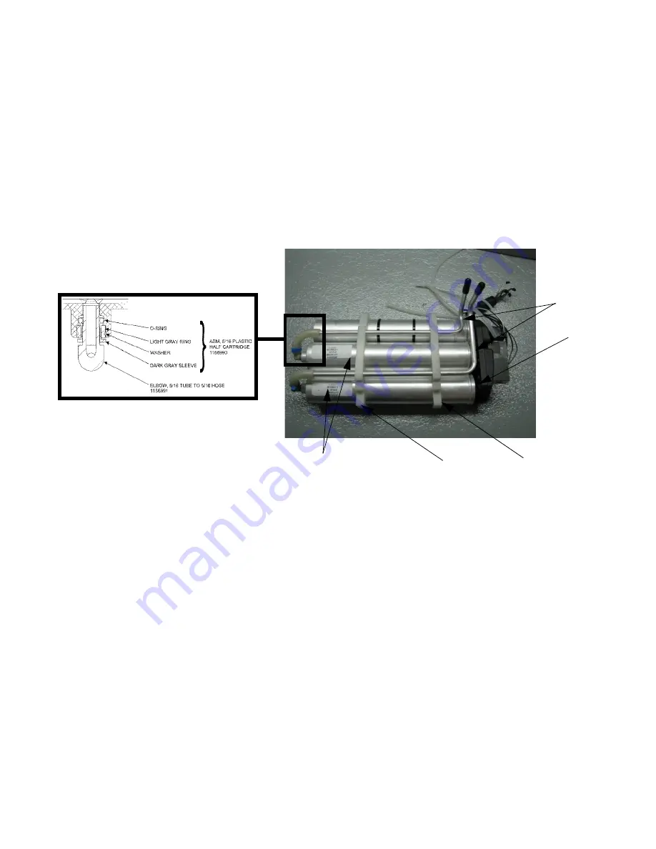
16 SIEVE BED MANIFOLD UNIT
Invacare® Solo2™ Portable Oxygen Concentrator
58
Part No 1176122
FIGURE
2
Heat Exchanger
Manifold
Upper Spacer
Sieve Beds
Page 1: ...manual The procedures in this manual MUST be performed by a qualified technician Invacare Solo2 Portable Oxygen Concentrator Model TPO100B Model TPO100B EU Model TPO100B UK Model TPO100B AZ EN Internal Repair Manual NL ...
Page 2: ...entrator User Manual Domestic 1156872 Invacare Solo2 Transportable Oxygen Concentrator Operator s Manual Europe 1163190 2012 Invacare Corporation All rights reserved Republication duplication or modification in whole or in part is prohibited without prior written permission from Invacare Corporation Trademarks are identified by and All trademarks are owned by or licensed to Invacare or its subsidi...
Page 3: ...ant Safety Information 13 Radio Frequency Interference 15 Polarized Plug Instruction 15 SECTION 4 PACKAGING AND HANDLING 16 Inspection 16 Storage 16 Disposal of Equipment and Accessories 16 SECTION 5 CHECKING O2 PURITY 17 Disposal of Equipment and Accessories 18 SECTION 6 ADMINISTRATIVE SETTINGS 19 Accessing Administrative Settings Screen 19 Resetting Patient Hours 20 Adjusting DC Power Limit 20 T...
Page 4: ...cle Filter 36 SECTION 9 REPLACING THE INLET FILTER 37 SECTION 10 REPLACING THE PATIENT OUTLET FILTER AND FILTER CONNECTOR 38 Replacing Patient Outlet Filter 38 Replacing Bulkhead Fitting 39 SECTION 11 ACCESSING INTERNAL COMPONENTS 40 Disassembly 40 SECTION 12 RIBBON CABLE 41 Disconnecting the Ribbon Cable 41 Connecting the Ribbon Cable 41 SECTION 13 BATTERY PACK 42 Removing the Battery Pack 42 Ins...
Page 5: ...cing the Battery Input Board 63 SECTION 21 INLET RESONATOR 64 Replacing the Battery Input Board 64 SECTION 22 P C BOARD COOLING FANS 65 Replacing the P C Board Cooling Fans 65 SECTION 23 COMPRESSOR BOX COOLING FANS 66 Replacing the P C Board Cooling Fans 66 SECTION 24 PULSE AND SENSITIVITY TEST 67 SECTION 25 TUNE AND TEST PROCEDURE 69 SECTION 26 LCD SCREEN NAVIGATION GUIDE 73 Turning Concentrator ...
Page 6: ...ently hazardous situation which if not avoided will result in death or serious injury WARNING Warning indicates a potentially hazardous situation which if not avoided could result in death or serious injury CAUTION Caution indicates a potentially hazardous situation which if not avoided may result in property damage or minor injury or both IMPORTANT Indicates a hazardous situation that could resul...
Page 7: ...Carry Handle On Off Button GREEN Indicator YELLOW Indicator RED Indicator LCD Display Increase Button External Power Input Connector Oxygen Outlet Port and HEPA Filter Air Intake and Filter The battery pack is not shown This item is located on the back side of the unit Decrease Button Mode Return Highlight Button ...
Page 8: ...oduct ETL Certified as Complying with ANSI AAMI ES60601 1 2005 ETL Certified Complying with CAN CSA C22 2 No 601 1 M 90 Canada EMC IEC 60601 1 2 Direct Current Type BF equipment Attention Consider Accompanying Documents DO NOT smoke No open flame or ignition sources Class II Double Insulated Power On Off DO NOT dispose of in household waste ...
Page 9: ... VDC Nom EXTERNAL POWER SUPPLY INPUT AC POWER SUPPLY DC POWER SUPPLY 120 VAC 50 60 Hz 2 5 amps 230 VAC 50 60 Hz 1 25 amps 11 16 VDC 12 6 VDC Nom 10 0 Amp max SOUND LEVEL 40 dBA weighted 2 LPM continuous and all pulse settings 1 5 ALTITUDE Up to 10 000 ft 3046 m above sea level Titration recommended for use above 10 000 ft 3046 m OXYGEN CONCENTRATION BASED ON AN ATMOSPHERIC PRESSURE OF 14 7 PSI 101...
Page 10: ... 0 5 through 3 0 LPM 0 psi 0 5 LPM increments All settings are 0 2 LPM 2 0 LPM max w Ext DC Power Cable MAXIMUM RECOMMENDED FLOWRATE WITH 7KPA 1 01 PSI BACKPRESSURE 3 0 LPM PRESSURE RELIEF ACTIVATION 20 psi 5 psi 137 8 kPa 34 5 kPa MAX OUTLET PRESSURE 3 0 LPM CONTINUOUS 12 0 psig DIMENSIONS WITHOUT CART 16 5 in high x 11 in wide x 8 in deep 41 9 cm high x 27 9 cm wide x 20 3 cm deep WEIGHT UNIT WI...
Page 11: ...PERATURE 41 F to 95 F 5 C to 35 C 2 F to 140 F 20 C to 60 C EXTENDED TEMPERATURE RANGE USING AC OR DC POWER OPERATING TEMPERATURE AC SUPPLY DC SUPPLY 95 F to 104 35 C to 40 C Unlimited use all settings all modes Unlimited use all settings with pulse mode Limited to 2 0 LPM or less with continuous mode EXTENDED TEMPERATURE RANGE USING BATTERY OPERATING TEMPERATURE 95 F to 104 35 C to 40 C Pulse Mod...
Page 12: ...hen compressed This compressed air is then directed toward one of two nitrogen adsorbing sieve beds Concentrated oxygen exits the opposite end of the active sieve bed and is directed into an oxygen reservoir where it is delivered to the patient in specific volumes during the inhalation portion of a detected breath The Invacare transportable oxygen concentrator is capable of operation by the patien...
Page 13: ...REDUCE THE RISK OF BURNS ELECTROCUTION FIRE OR INJURY TO PERSONS A spontaneous and violent ignition may occur if oil grease greasy substances or petroleum based products come in contact with oxygen under pressure These substances MUST be kept away from the concentrator tubing and connections and all other oxygen equipment DO NOT use any lubricants unless recommended by Invacare Avoid using while b...
Page 14: ...le is turned Off disconnect the car accessory power supply and remove the transportable oxygen concentrator from the automobile NEVER allow the transportable oxygen concentrator to be stored in a very hot or cold automobile or in other similar high or low temperature environments refer to Typical Product Parameters on page 8 DO NOT operate in temperatures below 41 F 5 C or above 104 F 40 C for ext...
Page 15: ...orrected by one of the following measures Reposition relocate or increase the separation between the equipment Connect the equipment into an outlet on a circuit different from that to which the other device s is connected DO NOT connect the concentrator in parallel or series with other oxygen concentrators or oxygen therapy devices Close supervision is necessary when this product is used near chil...
Page 16: ...ectronic Equipment WEEE Directive 2002 96 CE This product may contain substances that could be harmful to the environment if disposed of in places landfills that are not appropriate according to legislation Follow local governing ordinances and recycling plans regarding disposal of the device or components normally used in operation The device does not generate waste or residue in operation DO NOT...
Page 17: ...o 3 0 LPM continous refer to Solo2 User Manual allow to run for a minimum of 8 minutes 3 Connect a standard hand held oxygen analyzer to the outlet port 4 Follow the directions provided by the analyzer manufacturer 5 Repeat STEPS 2 4 for continuous flow settings 2 5 2 0 1 5 1 0 and 0 5 Oxygen purity should be checked every 3 years or 26 280 hours whichever comes first ...
Page 18: ...f in places landfills that are not appropriate according to legislation Follow local governing ordinances and recycling plans regarding disposal of the device or components normally used in operation The device does not generate waste or residue in operation DO NOT dispose of the device or the battery module in the normal waste stream The lithium battery module should be returned to your dealer pr...
Page 19: ...gs Screen From main menu operational screen DETAIL A simultaneously press the Mode Return Highlight Up Increase and Down Decrease Buttons to access the administrative settings screen DETAIL B ON OFF Button Mode Return Highlight Button Main Menu Operational Screen Down Decrease Button Up Increase Button Administrative Settings Screen DETAIL A DETAIL B ...
Page 20: ...ing DC Power Limit 1 Enter administrative settings screen DETAIL B Refer to Accessing Administrative Settings Screen on page 19 for this procedure 2 Locate the DC Power Limit setting DETAIL B A Press the Up Increase or Down Decrease button to highlight DC Power Limit setting B Press the Return Highlight button to relocate highlight bar to the adjustable setting on right side of screen 3 Press the ...
Page 21: ... or Down Decrease button to toggle between ON or OFF 4 Save changes by pressing the Return Highlight button to relocate highlight bar to left side of screen 5 Press and hold the Return Highlight button to return to the main menu operational screen The portable oxygen concentrator will automatically return to the main menu operational screen if idel for a period of approximately 10 15 seconds The p...
Page 22: ...mmunication exists between the Transportable Oxygen Concentrator and the battery DETAIL A by momentarily pressing the ON OFF button 3 Connect Transportable Oxygen Concentrator to AC power source Screen will light up displaying the AC power icon battery bars on battery symbol that correspond to the battery and the charging icon if battery is not at 100 DETAIL B DETAIL A DETAIL B DETAIL C ...
Page 23: ...l sound in 10 second intervals 9 Verify that the No Breath Found alarm is operating as defined by the Solo2 User Manual 10 Connect an oxygen cannula to the Transportable Oxygen Concentrator Refer to the Solo2 User Manual for this procedure 11 Breathe with the cannula to ensure the Transportable Oxygen Concentrator pulses at each setting DETAIL C will disappear Change setting as required 12 Turn un...
Page 24: ...for a minimum of 6 1 2 minutes 3 Attach a flowmeter to patient outlet 4 Measure flow for 2 minutes 7 3 Checking Compressor Inlet Filter 1 Remove inlet filter Refer to Replacing the Inlet Filter on page 37 for this procedure 2 Inspect filter if media is discolored replace inlet filter Refer to Replacing the Inlet Filter on page 37 for this procedure Recommended to be replaced between patients If fl...
Page 25: ... a continuous basis Some of these alarms have multiple sub codes available to the service technician that can be used to help diagnose the problem The alarms that carry sub codes are Compressor Alarm This alarm group centers on the compressor operation These are alarms for which there is no corrective action available to either the patient or the provider System Alarm This alarm group centers on i...
Page 26: ...n The first is the total number of errors occurring the second number is the error sequence current error displayed beginning with 0 and the last four numbers are the error codes Refer to Error Codes on page 27 If more than one error occurs use the Return Highlight button to If more than one error occurs use the Return Highlight button to cycle through each error Once the unit is turned off the al...
Page 27: ... at a lower rate 1536 Alarm Unit Temp HI LO Check ambient temp and blockage of air inlet outlet 1792 Warning Start Temp HI LO Check ambient temp and blockage of air inlet outlet 2048 Alarm Battery Temp HI LO Check ambient temp and blockage of air inlet outlet 2049 Alarm Battery Temp HI LO Check ambient temp and blockage of air inlet outlet 2304 Warning Low O2 Purity Check ambient temp and blockage...
Page 28: ...nsmit data from the MCU register out the RS232 port without success 2823 Alarm err Import eeprom During a request to read information from the GUI an invalid data size type was sent from the GUI The serial transmission might be noisy Check GUI SNAP statistics group for possible packet errors 2824 Alarm Recover upper The upper copy of the EEPROM memory does not match its checksum There are two copi...
Page 29: ...to get an event from the event queue a count is looked at to determine whether the event queue has any event in it An event either got lost event queue pointer is invalid or the event count is invalid 2834 Alarm ric Time out heap full IDF internal alarm The timeout heap RAM buffer is not large enough to hold the present number of timeouts needed to properly execute the code The timeout heap is sta...
Page 30: ...is held longer than 5 seconds The actual error code should not show up since after the alarm is decoded a processor reset will occur wiping out the alarm code 2844 Alarm pll is running in limp mode The normal processor clock frequency is not working A very slow limp frequency is being used so that the processor can at least notify the user of the problem Check the external crystal oscillator for t...
Page 31: ...o create a EEPROM mailbox for task EEPROM access within the DSPBIOS operation system The design of the code is not proper This is only possible with a change to the source code recompile and update to a new executable 2852 Lcd Mem alloc err Not applicable IDF internal alarm This code is reserved for Solo2 software development debugging 2853 Err Cal O2 open Applicable to Calibration Mode only The o...
Page 32: ...ander U10 might be damaged 2862 Alarm Wait for V12 on time out A request for the 12VDC supply to turn on failed to be acknowledged within a 1 second timeout period There could be a problem on the I2C bus The GPIO expander U10 might be damaged 2863 Alarm Gpio exp ddriver wait to acquire i2c time out GPIO expander was not able to acquire the I2C bus for a period of at least 5 seconds There could be ...
Page 33: ...evel This condition has a guard during a flow change of 6 shift counts This guard condition will prevent false low flow conditions from being detected whenever the user changes the Continuous Mode setting Check to see that the proportional valve plumbing is correct Check to see if the proportional valve is working correctly 4099 Maximum Shift Time Exceeded The time it took the sieve beds to shift ...
Page 34: ...tting in 6 seconds this alarm will occur Check to see that the rotor on the compressor rotates freely 3330 Alarm Power on but compressor shutdown If during shutdown the power state variable within the software shows the unit should be on but has somehow shutdown normally this alarm will occur This alarm indicates a possible software programming error The power state software variable does not repr...
Page 35: ...e 24 hours per day 7 days per week for 6 months 26 280 hours are equivalent to usage 24 hours per day 7 days per week for 3 years PREVENTATIVE MAINTENANCE RECORD TRANSPORTABLE OXYGEN CONCENTRATOR ON EACH INSPECTION Record Date of Service Record Elapsed Hours On Hour Meter Clean Cabinet Filter s Check Prescribed L min Flow Rate EVERY 26 280 HOURS OR 3 YEARS WHICHEVER COMES FIRST Check Oxygen Concen...
Page 36: ...ce filter and filter cover 6 Install the filter cover ensuring the tabs click holding the filter cover in place CAUTION To insure proper operation and avoid voiding unit warranty only use Invacare supplied components The gross particle filter should be cleaned or replaced per the Solo2 Preventative Maintenance Record CAUTION DO NOT operate the Solo2 without filters installed DO NOT clean the filte...
Page 37: ... the inlet filter access door to unit 3 Remove the filter access door from the unit 4 Locate the existing inlet filter and remove 5 Install the replacement inlet filter 6 Reinstall inlet filter access door by inserting tabs into slots located on the unit 7 Reinstall retaining screw to secure the inlet filter access filter door The inlet filter should be replaced per the Preventative Maintenance Re...
Page 38: ... the patient outlet filter 2 Place fingers on patient outlet filter and turn counter clockwise to loosen 3 Remove patient outlet filter and o ring from unit 4 Install new o ring onto unit 5 Install new patient outlet filter onto unit 6 Hand tighten filter until secure The patient outlet filter should be replaced according to the Solo2 Preventative Maintenance Record Use Invacare P N 1164372 Patien...
Page 39: ...ove the 4 screws that secure the control panel to the Solo2 shroud Detail B 3 Remove the 2 screws that secure the handle to the Solo2 unit Detail B 4 Remove the Patient Outlet HEPA filter 5 Disconnect the Tubing from the Patient Outlet Fitting Detail D 6 Take a 1 1 8 notched socket and place over and loosen the nut on the Outlet Fitting 7 Reassemble the unit in reverse order Indication Labels DETA...
Page 40: ...il B using the Torx T15 screwdriver from the control panel 4 Lay the unit face down as shown in Detail C 5 Remove and retain the 6 19 x 50 Plastite screws in Detail C using the Torx T15 screwdriver 6 While holding onto the front and back shrouds flip the unit over onto the back shroud as seen in Detail D ensuring the ribbon cable is not pulled apart from the unit WARNING Ensure the battery pack an...
Page 41: ...e unplugged 6 Unplug the Ribbon Cable from the Control Panel P C Board 12 2 Connecting the Ribbon Cable 1 Reverse STEPS 1 6 in the above procedure to connect the Ribbon Cable to the P C Board 2 Make sure the cable ends are plugged back in per Details A and B CAUTION Before handling the P C Board ensure you are properly grounded to prevent static discharge and damage to the components of the P C Bo...
Page 42: ...1 Locate the battery pack on the back of the Solo2 detail A 2 Lift the handle out of the way of the battery pack 3 Find the slotted handle located on the top of the battery pack and pull upward until battery is free detail B and C Handle DETAIL A Battery Pack Handle DETAIL B Unit with Battery Pack Removed Battery Pack DETAIL C ...
Page 43: ...shroud as shown in Details D and E 4 Check the alignment of the battery pack If alignment is off pull battery back up slightly and reposition until the battery pack is flush with both the top and bottom of the rear shroud 5 Verify the battery is in contact with the electrical connections by turning the unit on If power up occurs the unit is working correctly If power up does not occur repeat STEPS...
Page 44: ...embling the battery pack make sure that no exposed connectors touch each other otherwise shorts of the individual batterys may occur If the battery pack does not charge or the Solo2 does not power up in the required time as stated in Product Parameters replace all battery packs If the battery label rips during removal remove the serial number label and replace the battery label with a new one Appl...
Page 45: ...o the slot on the side of the battery box 5 Ensure that all wire after pushing down into the slot are not above the surface and place the cover On the other half of the shroud and screw the cover back together using the T 10 Torx screwdriver 6 Replace the Battery label and serial number When replacing batteries because of problems with unit performance replace all three batteries DO NOT mix used a...
Page 46: ...ide only 4 With the wires and tubes disconnected remove the screws holding the P C Board to the compressor sound box CAUTION Before handling the P C Board ensure you are properly grounded to prevent static discharge and damage to the components of the P C Board A static strap MUST be worn and properly grounded using an alligator clip Electrical conduit or a water pipe can bue used if a ground is u...
Page 47: ...vacare Solo2 Portable Oxygen Concentrator FIGURE 1 O2 Sensor Ribbon Cable Tubing from Manifold to P C Board P C Board Compressor Connector Battery Communication Cable White External Power Inlet Battery Power Cable P C Board Cooling Fans ...
Page 48: ...14 P C BOARD Invacare Solo2 Portable Oxygen Concentrator 48 Part No 1176122 FIGURE 2 Wires from Valves encased in Ferrite Bead O2 Sensor Pressure Transducer Flow Sensor ...
Page 49: ...art No 1176122 49 Invacare Solo2 Portable Oxygen Concentrator FIGURE 3 Mounting Screw Flow Restrictor DO NOT REMOVE Mounting Screw Mounting Screw Current production P C Board P N 1166960 for use with Aspen Motor ONLY ...
Page 50: ...n Motor Current Solo2 Units with Aspen Motor Three Inductors in place on P C Board used with Thomas Motor Out of production Solo2 Units with Thomas Motor The Aspen and Thomas motors are not interchangeable Damage to the Solo2 P C Board will occur if the board and motor are not properly matched The Aspen motor was implemented on unit Serial Number 10IF00F010 ...
Page 51: ...GURE 5 CAUTION Before handling the P C Board ensure you are properly grounded to prevent static discharge and damage to the components of the P C Board A static strap MUST be worn and properly grounded using an alligator clip Electrical conduit or a water pipe can bue used if a ground is unavailable Care should be taken to ensure that the alligator clip contacts bare metal surface For this procedu...
Page 52: ...ressure connections as shown in Figures 6 and 7 FIGURE 6 FIGURE 7 Flow Sensor Ensure tubes are routed as shown O2 To Patient Outlet Flow Sensor Restrictor Oxygen Sensor Pressure Transducer P E Valve Proportional Valve Conserver Valve Flow Sensor Oxygen Sensor Valve Pressure Transducer Tie wraps Tie wraps ...
Page 53: ...rx T15 Detail C 8 Cut the Ty wrap off the tube in the lower shroud that goes from the compressor to the 4 way valve Detail A 9 Lift the compressor and 4 way valve assembly out of the compressor box lower shroud Detail E and F 10 Cut the Ty wraps that secure the tubes from the4 way valve to the compressor and separate the valve from the compressor Detail A 11 Pull the compressor out of the Gray sou...
Page 54: ...aust vent tube is connected between the compressor box and the rear shroud Detail D 16 Reassemble the unit in reverse order FIGURE 1 DETAIL A DETAIL B Cut Tie wrap and replace during assembly DETAIL C DETAIL D Vibration mounts 3 32 Hex Head screw top shroud Compressor Box Mounting Screws Exhaust vent tube not shown 3 32 Hex Head screw bottom shroud ...
Page 55: ...rt No 1176122 55 Invacare Solo2 Portable Oxygen Concentrator FIGURE 2 4 Way Valve Disconnect tubes at compressor Compressor Foam Wrap Fan Foam Wrap Muffler DETAIL E DETAIL G DETAIL F Fans mounted behind the compressor ...
Page 56: ...r off the Sieve Bed 9 With the Sieve Bed Manifold out of the Solo2 out of the Solo2 take the wrench and remove the Sieve Bed from the manifold 10 Remove the second Sieve Bed from the manifold 11 Do not remove the product tank from the Manifold 12 Install the new Sieve Beds one at a time and torque to 7 5Inch lbs then install the seconds and repeat the torque if the beds are over torqued the unit m...
Page 57: ...Make sure the open ends of the Heat Exchanger are plugged until ready to install into the Solo2 17 Install the Sieve Beds into the unit and hook up wires and tubing in reverse order FIGURE 1 Sieve Bed Tubes attached to Heat Exchangers Manifold Power Connections Sieve Bed Manifold Combo Heat Exchanger Valve wire pin out from Manifold Numbers located on board V1 4 way V4 Flow Sensor V2 Conserver V5 ...
Page 58: ...16 SIEVE BED MANIFOLD UNIT Invacare Solo2 Portable Oxygen Concentrator 58 Part No 1176122 FIGURE 2 Heat Exchanger Manifold Upper Spacer Upper Spacer Sieve Beds ...
Page 59: ...ining up the mounting holes for the screws 5 Connect the ribbon cable to the LCD display as shown in Detail B 6 With spacers in place attach the control panel with screws Tighten carefully DO NOT overtighten CAUTION Before handling the P C Board ensure you are properly grounded to prevent static discharge and damage to the components of the P C Board A static strap MUST be worn and properly ground...
Page 60: ...it to dry completely to ensure a good seal of the replacement label 4 Install the new control panel label 5 Press firmly on the perimeter surfaces of the label Invacare recommends using isopropyl alcohol to remove residual glue from the top of the unit The use of any other type of household or industrial cleaner will cause damage to the unit and should not be used CAUTION DO NOT press directly on ...
Page 61: ...ssor to the 4 way valve Detail A 7 Cut the Tie wraps that secure the tubes from the 4 way valve to the compressor and separate the valve from the compressor Detail A 8 Remove and replace the existing 4 way valve CAUTION Before handling the P C Board ensure you are properly grounded to prevent static discharge and damage to the components of the P C Board A static strap MUST be worn and properly gr...
Page 62: ...he muffler assembly out of the compressor box and disconnect from the tube 6 Install a replacement muffler and place into the compressor box CAUTION Before handling the P C Board ensure you are properly grounded to prevent static discharge and damage to the components of the P C Board A static strap MUST be worn and properly grounded using an alligator clip Electrical conduit or a water pipe can b...
Page 63: ...ve the compressor box assembly and DO NOT remove any parts from inside it 5 Using a T 10 remove the screws that secure the battery input board to the rear shroud 6 Disconnect the wire harnesses on the existing battery input board and install on the replacement battery input board 7 Attach the battery input board with harnesses to the rear shroud 8 Tighten the screws Rear Shroud Battery Input Board...
Page 64: ... the Solo2 unit 3 Disconnect the tube at the base of the resonator that feeds the compressor 4 Attach the new resonator to the tube coming from the compressor 5 Place the resonator back into the Solo2 feeding the tubing as show 6 Reassemble the unit and test to ensure Solo2 is operating correctly Tube attaches from compressor here Rear Shroud Resonator DETAIL A DETAIL B DETAIL C To Inlet Filter To...
Page 65: ...ng that is not working Detail B 6 Unplug the non operational fan from the working fan or remove both if both are not operating 7 Replace the fans and harness tie wraps and reassemble the Solo2 then test to ensure the fans are operational CAUTION Before handling the P C Board ensure you are properly grounded to prevent static discharge and damage to the components of the P C Board A static strap MU...
Page 66: ...errite Bead and keep to reinstall on the new fans 8 Install the new fans into the sound foam and feed wires through and install the Ferrite 9 Once the unit is assembled up to the section just before the 2 shrouds are attached together turn the unit on and verify the fans are operational CAUTION Before handling the P C Board ensure you are properly grounded to prevent static discharge and damage to...
Page 67: ...ress continue button on the screen The program will monitor the TPOC and display values on the screen 13 When the screen displays a green Pass change the TPOC setting to Setting 2 by pressing the Plus button on the TPOC control panel Press the continue button on the conserver test station The program will monitor the TPOC and display values on the screen 14 When the screen displays a green Pass ch...
Page 68: ... 5 settings on the Traveler Verify the values are within the ranges specified on the Traveler 19 Unplug the unit from the AC DC power source The pass indicator should be achieved within 2 minutes after the TPOC has been turned to the correct flow setting If not press Continue button Test will pass if the data is within the acceptance criteria limits ...
Page 69: ...25 TUNE AND TEST PROCEDURE Part No 1176122 69 Invacare Solo2 Portable Oxygen Concentrator 25 Tune and Test Procedure Tools Required GUI battery housing O2 Flow sensor test station AC DC power supply ...
Page 70: ...g and the exhaust is not blocked Let the unit run for 5 minutes at 3 LPM Continuous 9 Verify GUI is functioning by clicking CLEAR SNAP STATISTICS in the upper right hand corner values in fields above button should zero then begin populating with values a couple seconds later Check the flowrate on the Concentrator Test program Click the Press to Reset button and wait about 30 seconds The average mu...
Page 71: ... minutes Note PETA and PET D values must equal 590 to 610 O2 Stability should be within 1 but can be up to 1 6 maximum at 3 0LPM 21 Record the O2 and Flowrate 22 Change the unit flow mode setting from pulse to continuous 2 5 LPM 23 At 2 5 LPM check the flowrate on the Concentrator Test program Click the Press to Reset button and wait about 30 seconds The average must be between 2 5 25 LPM 2 25 2 7...
Page 72: ...25 TUNE AND TEST PROCEDURE Invacare Solo2 Portable Oxygen Concentrator 72 Part No 1176122 Flow Setting Motor RPM Pressure Output 3 0 2700 12 2 5 2300 11 2 0 1600 9 1 5 1300 8 5 1 0 875 7 5 0 5 700 7 5 ...
Page 73: ...Screen Navigation After turning on unit press and hold the Mode Return Highlight Button to scroll through the three SOLO2 concentrator menu screens 26 3 Normal Operating Standby Screen The Normal Operating Standby screen shows either battery strength guage fan operating external power on and battery charging icons when applicable or the current last mode of operation and output flow level selected...
Page 74: ... highlight bar is on the LEFT SIDE of the screen to move the highlight bar up or down Tap the Up Increase Button or Down Decrease Button while the highlight bar is on the RIGHT SIDE of the screen to change the value of the item highlighted Hold down the Mode Return Highlight Button to continue scrolling through the three menu screens 2 To save changes made on the LCD Adjust screen press and hold t...
Page 75: ...ng Flow 1 With the Mode Flow screen displayed press and hold the Up Increase Button or Down Decrease Button until desired setting is achieved 2 Wait until the Mode Flow screen flashes three times To adjust either the mode of flow the Mode and Flow Adjust Screen must be displayed If the battery level screen is displayed press the Mode Return Highlight Up Increase or Down Decrease button for approxi...
Page 76: ...acare Corporation USA One Invacare Way Elyria Ohio USA 44036 2125 800 333 6900 Canada 570 Matheson Blvd E Unit 8 Mississauga Ontario L4Z 4G4 Canada 800 668 5324 Part No 1176122 Rev A 2 12 www invacare com ...