Thermal/Mechanical Specifications and Design Guide
89
PECI Interface
In the event that the processor is tri-stated using power-on-configuration controls, the
PECI client will also be tri-stated. Processor tri-state controls are described in the
relevant sections of the Datasheet listed in
7.1.5.2
Device Discovery
The PECI client is available on all processors. The presence of a PECI enabled processor
in a processor socket can be confirmed by using the Ping() command described in
. Positive identification of the PECI revision number can be achieved by
issuing the GetDIB() command. The revision number acts as a reference to the PECI
specification document applicable to the processor client definition. Refer to
for details on GetDIB response formatting.
7.1.5.3
Client Addressing
The PECI client assumes a default address of 0x30. The PECI client address for the
processor is configured through the settings of the SOCKET_ID[1:0] signals. Each
processor socket in the system requires that the two SOCKET_ID signals be configured
to a different PECI addresses. Strapping the SOCKET_ID[1:0] pins results in the client
addresses shown in
. These package strap(s) are evaluated at the assertion
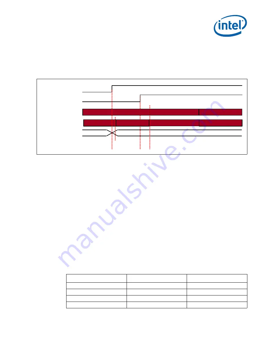
of PWRGOOD (as depicted in
The client address may not be changed after PWRGOOD assertion, until the next power
cycle on the processor. Removal of a processor from its socket or tri-stating a processor
will have no impact to the remaining non-tri-stated PECI client addresses.
Figure 7-44. Intel
®
Core™ i7-3960X, i7-3970X Processor Extreme Edition, Intel
®
Core™ i7-
3930K Processor, and Intel
®
Core™ i7-3820 Processor PECI Power-up
Timeline()
PWRGOOD
RESET_N
Core execution
idle
running
Reset uCode
Boot BIOS
PECI Client
Status
Data Not Ready
Available except core
services
SOCKET_ID[1:0]
X
SOCKET ID Valid
In Reset
Fully Operational
In Reset
Table 7-18. SOCKET ID Strapping
SOCKET_ID[1] Strap
SOCKET_ID[0] Strap
PECI Client Address
Ground
Ground
0x30
Ground
V
TT
0x31
V
TT
Ground
0x32
V
TT
V
TT
0x33
Summary of Contents for BX80619I73820
Page 10: ...10 Thermal Mechanical Specifications and Design Guide...
Page 14: ...Introduction 14 Thermal Mechanical Specifications and Design Guide...
Page 104: ...Thermal Solutions 104 Thermal Mechanical Specifications and Design Guide...
Page 112: ...Mechanical Drawings 112 Thermal Mechanical Specifications and Design Guide...
Page 118: ...Socket Mechanical Drawings 118 Thermal Mechanical Specifications and Design Guide...
Page 124: ...Package Mechanical Drawings 124 Thermal Mechanical Specifications and Design Guide...


