background image


Minimate Pro Operator Manual 

7

–1 

7.  O

PTIONAL 

F

EATURES


7.1. 

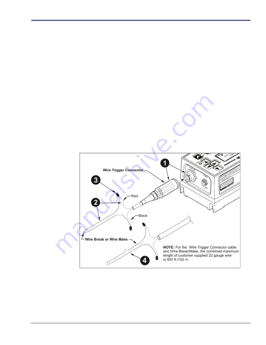
Wire Break/Make Trigger Cable [Optional] 

The optional 

Wire Break/Make Trigger Cable

 (Part No. 720A3501) for the 

Series IV

 units is 

available for purchase from your authorized 

Instantel Dealer Representative

 and is shipped with 

an installation and setup sheet.  The 

Wire Break/Make Trigger Cable

 is used to trigger up to six 

Minimate Pro

 units; a 

Wire Break/Make Trigger Cable

 is required for each unit to be triggered. 

The units auxiliary channel senses the wire trigger signal via a 22 gauge 

Break

 or 

Make

 wire 

provided by the operator, and starts recording. A signal occurs when the 

Break

 or 

Make

 trigger 

wires separate or create a contact, 

a)

 a 

Break

 signal from a blast physically breaking the trigger 

wire, or 

b)

 a 

Make

 signal occurs when the trigger wires contact, such as an operator pressing a 

push button switch.


Tools and Materials Required: 

1.


Series IV

 Unit(s) – up to six units may be connected 

2.


Wire Break/Make Trigger Cable

, one for each unit (Part No. 720A3501), with 

instructions 

3.


Red and Black 22 Gauge Wire, up to 500 ft./152 m 

4.


Wire Strippers 

5.


A Two-way Switch, for each 

Make 

trigger setup 

6.


Electrical tape, as required 


Single Wire Break/Make Trigger Cable Setup 


Summary of Contents for Minimate Pro Series

Page 1: ......

Page 2: ...efine such an extension of responsibility and liability Any shipments returned directly to Instantel Inc must have our prior approval and all packages must display the Return of Material Authorization...

Page 3: ...Life 2 5 3 Handling Precautions 3 1 4 Unit Label Instructions 4 1 4 1 Condensed Instructions 4 1 4 2 Battery Shipping and Warranty Instructions 4 1 5 Introduction 5 1 5 1 Event Monitoring Example 5 1...

Page 4: ...1 Why Calibration is Important 10 1 10 1 2 What the Calibration Certificate Means 10 1 10 1 3 Importance of Manufacturer Certified Calibration 10 1 10 1 4 Minimate Pro Sensor Check Feature 10 1 10 2...

Page 5: ...Monitor Software Version Number ISEE Geophone Serial Number s DIN Geophone Serial Number s ISEE Linear Microphone Serial Number Dealer Name Date Purchased 1 3 Complete and Return Your Registration Ca...

Page 6: ...nt Directive WEEE This product contains electrical or electronic materials including batteries The presence of these materials will have adverse effects on the environment and human health if not disp...

Page 7: ...ery life conservation Turn the battery on for use or charging by simply plugging in the provided AC Adapter to the unit and an electrical outlet and pressing the On Off key If you are in the field or...

Page 8: ...run in the Maintenance menu Self Check reference Section 9 6 e option The unit will prompt to repair any errors found during the File System Check If this is the case accept the disclaimer notice and...

Page 9: ...e amount of memory and the battery level Memory and Battery icons are also located at the lower part of the main display window which are visible once the unit has started The Memory icon displays inc...

Page 10: ...Enter key to return to the Maintenance menu 2 3 Battery Instructions 2 3 1 Charging The Minimate Pro internal battery requires regular and periodic charging To charge the battery plug the supplied AC...

Page 11: ...al life expectancy of the battery 70 of initial capacity is 300 cycles Li Ion batteries do not experience a memory problem if left on charge all the time The typical charge retention 80 of initial cha...

Page 12: ...2 6 Minimate Pro Operator Manual Notes...

Page 13: ...s charge the battery when fewer than two graph bars appears in the display or immediately when the Minimate Pro beeps If possible when not in use keep the Minimate Pro on charge Instantel s supplied c...

Page 14: ...3 2 Minimate Pro Operator Manual Notes...

Page 15: ...aneously holding down the Up Arrow and Enter keys for 3 seconds While still holding down these keys press the On Off key Note B If you change your sensors it is important to update the system after th...

Page 16: ...4 2 Minimate Pro Operator Manual Notes...

Page 17: ...features as they are released by Instantel through the Blastware Compliance Module the software companion provided with your monitor The Minimate Pro operates as a basic compliance monitor with intuit...

Page 18: ...Blasting by David E Siskind Ph D published by ISEE ISBN 1 892396 11 4 5 The Effects of Vibrations and Environmental Forces by Lewis L Oriard published by ISEE ISBN 1 892396 10 6 6 Construction Vibrati...

Page 19: ...channels The Minimate Pro4 model offers four recording channels and can be set up with one Series IV Triaxial Geophone ISEE or DIN and an ISEE Linear Microphone A second model the Minimate Pro6 offers...

Page 20: ...trument Minimate Pro4 Minimate Pro6 Standard Features Number of Channels 4 Channels ISEE or DIN Geophone and an ISEE Linear Microphone 6 Channels ISEE or DIN Geophone on both connectors or an ISEE or...

Page 21: ...Ethernet Communication Cable Minimate Pro to PC Part No 720A4101 Optional Features Refer to the Chapter Optional Features in this manual for more information Vibration Dose Value VDV Monitor Mode Requ...

Page 22: ...2 geophones Full Waveform Recording Record Modes Waveform Manual Waveform and programmed Start Stop Record Time 1 to 9 000 seconds programmable in one second steps plus a 0 25 seconds pre trigger Aut...

Page 23: ...4 to 113 F Electronics 40 to 45 C 40 to 113 F Battery 20 to 45 C 4 to 113 F ISEE Microphone 20 to 50 C 4 to 122 F ISEE and DIN Geophone 40 to 50 C 40 to 122 F Water Resistance IPC67 submerse to 30 cm...

Page 24: ...r Manual 6 3 Minimate Pro Physical Attributes Make additional copies of the image below It may be used as a template for mounting the unit to a surface or within a security box for long term or remote...

Page 25: ...ading you choose the backlight color option and timeout settings for battery conservation Intuitive Interface Graphic icons keep you informed of battery and memory levels and dynamic display of Peak V...

Page 26: ...les Purchase the Blastware Advanced Module to view histogram data in real time Remote Connectivity Use the Auto Call Home program for easy remote access to your monitor and data using Serial or IP com...

Page 27: ...onnectors and sealed electronics to enhance water resistance Series IV monitors offer an added level of EMI shielding built in noise and anti aliasing filtering both sensor ports are isolated from the...

Page 28: ...e Alarm and Modem to the unit simultaneously 720A3101 RS 232 Communication Cable Connect a Series IV instrument to a 9 pin serial port on the PC 71407001 USB Serial Adaptor Cable Use a USB Adaptor to...

Page 29: ...ter Connect the Minimate Pro to your vehicles 12 volt power supply or a 12 volt battery for remote installations 370 000002 000 PS 12 1 0 12V 1 0A AC For use with Series IV units 720A3601 Null Modem C...

Page 30: ...Manual start key to monitor an Event Cancel Cancel Back or Exit Enter Enter Save Accept Menu Up Down Arrows Next Prev Scroll through Menus or Text Entry Hold down to scroll quickly Right Arrow Edit Ac...

Page 31: ...rows to move to and from each character location for editing Press the Enter key to Save the changes or the Cancel key to return to the previous menu without saving the changes 4 Within the View Data...

Page 32: ...ev Next Event data or the Cancel key to go Back to the previous menu ii Press the Right Arrow key to review more data associated with the selected Event or the Cancel key to go Back to the previous me...

Page 33: ...te the Type of file it is as indicated below NOTE In the picture above two Events have a P as part of their designation this indicates that the Event was copied and subsequently Processed by using the...

Page 34: ...6 16 Minimate Pro Operator Manual...

Page 35: ...ire trigger signal via a 22 gauge Break or Make wire provided by the operator and starts recording A signal occurs when the Break or Make trigger wires separate or create a contact a a Break signal fr...

Page 36: ...e from your authorized Instantel Dealer Representative and is provided with an installation instruction sheet The Remote Alarm Controller indicates normal and over triggering at a remote site Use an o...

Page 37: ...k standard of communication protocol that is primarily used for Local Area Networks LAN to connect end systems in this instance the Series IV units to a network To use this feature a telephone cellula...

Page 38: ...nattended monitoring of noise such as building activities construction traffic and mining operations It is now possible to combine noise and vibration monitoring on the same unit making the Minimate P...

Page 39: ...crophone s to the Minimate Pro4 or Minimate Pro6 which allows for the use of two microphones as shown below 2 Minimate Pro Microphones come with a three sectional mounting stand Refer to the instructi...

Page 40: ...ess the Right Arrow to select either Fast or Slow d Press Enter to accept the new settings or Cancel to return to the Setup menu 10 Within the Setup menu ensure that the Sample Rate Trigger Level and...

Page 41: ...that event on the display 2 To view other recorded data on the unit press Down Arrow from the main display and highlight the desired event 3 Press Right Arrow three times to display the results of the...

Page 42: ...is set as 33 dB which is 3 dB above the minimum detectable sound level This provides a margin against false triggering by self generated noise 5 Overload Indicator Input that is greater than 140 dB i...

Page 43: ...o the factory or to an authorized Instantel Calibration Site There is no internal access to the batteries that provides for user maintenance without disassembly of the monitor and breach of warranty a...

Page 44: ...7 10 Minimate Pro Operator Manual Notes...

Page 45: ...ed USB hardware device lock is shipped with the Advanced Module which allows access to additional tools and processes 2 Follow the installation instructions within the Blastware Operator Manual Step 2...

Page 46: ...20A4101 please refer to that section of this manual for setup instructions otherwise this tutorial assumes that you are using the supplied serial communications cable and USB adaptor Step 4 Turn the U...

Page 47: ...roductory battery and memory screens display the main display screen will appear showing that the Geophone and Linear Microphone if attached or additional Geophone if you have purchased the Minimate P...

Page 48: ...munications 1 Ensure that the check box for Series IV is selected at the lower left of the Blastware software window as follows 2 This tutorial assumes that you are using the supplied serial communica...

Page 49: ...Arrow key until View Edit Preferences is highlighted Press the Enter key 3 Press the Down Arrow key until Serial Baud Rate is highlighted 4 If the value to the right of Serial Baud Rate is not 115200...

Page 50: ...left mouse button If you have a Minimate Pro6 and have a second geophone attached to the monitor you can select an associated graph by using the dropdown menu for Compliance Graph for Geophone 2 4 All...

Page 51: ...has successfully been sent to the unit the following message will appear Select OK to return to the Compliance Setup dialog Step 9 Creating a Sample Event Refer to Section 6 5 Unit Keypad and Menu Na...

Page 52: ...gs used to record the Events for easier identification 5 Press the Right and Left Arrow keys to navigate the text field and the Up or Down Arrow keys to Change the characters Upper and lowercase alpha...

Page 53: ...is triggered during that delay the display is not updated Below is an example of the two Peak and ZC Frequency readouts that are dynamically displayed 11 Press the Cancel key to stop recording and the...

Page 54: ...ted Event or the Cancel key to go Back to the previous menu ii Press the Right Arrow key to review more data associated with the selected Event or the Cancel key to go Back to the previous menu Step 1...

Page 55: ...g the Copy Print icon The Copy and Print All Events dialog box appears Press the Yes button to copy all the Events on the unit and display them in the Events List Box Click on the Print checkbox to pr...

Page 56: ...g The results for the Self Check feature will also appear here if you have turned it on please refer to the Self Check section of this manual for more information on this diagnostic tool An example Mo...

Page 57: ...lling Scroll through the Event Click on the scroll bars Arrows to scroll through the Event Report 2 View the Entire Event Click on the File Menu and choose the Print Preview command The entire Event R...

Page 58: ...8 14 Minimate Pro Operator Manual Below is an example of a Series IV Event Report using the Waveform Record Mode...

Page 59: ...ram has a different icon a Within the View Data window select the Right Arrow key to display the Detail of a selected Event Below is an example of the Detail feature for a Waveform Event i Press the R...

Page 60: ...Press the Cancel key to return to the Main Display NOTE The settings and data may vary from the examples shown above dependent on the Setup File used or Event viewed 4 While viewing the Detail of an E...

Page 61: ...or delete Press the Enter key to access the popup menu 3 Press the Up or Down Arrow key to highlight Select Current Setup to use the file as the default setup or Delete Setup File to permanently remo...

Page 62: ...nd press the Up or Down Arrow keys on the unit to highlight the operator you would like to delete Press the Enter key to access the Menu Press the Up or Down Arrow keys on the unit to highlight Delete...

Page 63: ...the optional Vibration Dose Value VDV available with the purchase of the Blastware Advanced Module A Record Mode determines how the Minimate Pro records Events Refer to Trigger Level Record Time and...

Page 64: ...de setting 4 Press the Enter key to Save the new Current Setup by overwriting the name displayed or by creating a new Setup File name 5 Press the Cancel key to return to the Ready to Monitor display 1...

Page 65: ...e updated with the Peak and ZC Frequency information Press the Up Arrow key to turn them on again 2 Record Mode Waveform Manual Use Waveform Manual Record Mode option and Start Monitor key if automati...

Page 66: ...ocess manually if you have selected the Waveform Manual Record Mode otherwise the unit will start monitoring using the parameters set in the Setup and Preferences menus such as the External Trigger op...

Page 67: ...um For each channel the maximum peak and its frequency are calculated Also the largest peak vector sum is calculated over the entire Event NOTE The Histogram Record Mode consumes more battery power th...

Page 68: ...in the Preferences menu Refer to Sensor Check under the View Edit Preferences Section of this manual to learn more about the feature and to determine when it will be activated The Sensor Check settin...

Page 69: ...ize setting located within the Record Mode menu The unit continues to sample data continuously at the chosen sample rate but only stores the relevant peaks for the selected Interval Size This reduces...

Page 70: ...d Mode has been selected and the Event recording begins the unit will briefly display the following message NOTE A message Sensor Check will appear if it has been activated in the Preferences menu Ref...

Page 71: ...30 seconds then the Event Peak Vibration 1 Min Peak Vibration and 30 Second Peak Vibration values can be viewed by pressing the Right Arrow key for each as shown below 6 If a Waveform recording is tr...

Page 72: ...astware Operator Manual for more information on how to download weight files to the unit While monitoring the unit differentiates the velocity data into acceleration applies the frequency weighting an...

Page 73: ...ran Vert Vert Long Tran Long or Tran Vert Long This selection should be based on the time of day you are monitoring 9 Press the Enter key again to Save the new Current Setup by overwriting the name di...

Page 74: ...s located on the side of the Minimate Pro and is labeled Pressure The color of the label is red 1 Scroll down to highlight Pressure Sensor 2 Press the Right Arrow key to either select the ISEE Linear...

Page 75: ...Detection Error you must decide whether or not to Accept or Cancel the setup and fix the issue Suggested sensors and sample rates are also displayed in Blastware when you use the Unit Monitoring dialo...

Page 76: ...key 2 Continue to press the Right Arrow key to change the sample value 3 Press the Enter key to Save the changes or the Cancel key to return to the previous menu without saving the changes f Trigger L...

Page 77: ...ggered You can choose between a Fixed Time setting or an Auto Record setting Fixed Time sets the record time to a specified length For example you set the unit to record for two seconds once the recor...

Page 78: ...option is highlighted 4 Press the Right Arrow key to access this menu selection 5 The first selection is Record Stop Mode 6 Press the Right Arrow key to toggle between Auto Record or Fixed Time 7 Pres...

Page 79: ...and sent to the unit Please refer to the Blastware Operator Manual for more information on the Monitor Scheduler feature Ensure that the Monitor Scheduler is On by activating it within Blastware Unit...

Page 80: ...ssure Trigger Level This allows for the triggering of a second alarm at the higher level For example in pile driving operations the remote alarm triggers a warning when activity exceeds the trigger le...

Page 81: ...ave the edits to each selection The Warning Alarm and Alarm Hold Time have a 300 second time limit 5 minutes If it is set to 0 then the user will need to manually press the Enter key 7 Highlight the A...

Page 82: ...ion is to predict Peak Particle Velocities PPV when the energy released is a variable Turn the Scaled Distance feature On to include the input and calculated Scaled Distance information with each Even...

Page 83: ...Arrow key to edit this field 8 Press the Right and Left Arrow keys to navigate through the Range values 9 Press the Up and or Down Arrow keys to change the values within the Enter Charge Weight value...

Page 84: ...to return to the previous screen 8 The unit briefly displays Reading Location from GPS 9 The unit than prompts Select Way Point of Sensor Name Select Read GPS Location by pressing the Enter key or the...

Page 85: ...up to 40 characters 5 Press the Enter key to Save the file or the Cancel key to return to the previous screen n General Notes The General Notes feature lets you include notes describing an Event You...

Page 86: ...how the interface is setup such as the units used imperial or metric and display and sound options These options are setup and saved but not to a specific file The monitor continues to operate with th...

Page 87: ...r Check is performed after each Event and added to each Events data 2 Press Enter key to Save any changes or the Cancel key to return to the Preferences menu or 3 Press the Sensor Check key to perform...

Page 88: ...Setup but the message below it states that and ISEE Triaxial Geophone has been Detected Press the Enter key to Accept the setup as shown and proceed to monitor or press the Cancel key to exit and edi...

Page 89: ...appear with each recorded Event Calculating the Natural Frequency of a Geophone Damping Overswing Ratio OR The OR measures damping and is calculated by computing the ratio of the magnitude of adjacen...

Page 90: ...ication link 1 Within the Preferences menu of the Minimate Pro press the Right Arrow key to access the Serial Baud Rate field 2 Continue to press the Right Arrow key to cycle through the communication...

Page 91: ...sure that the LCD display will turn off after 2 minutes of no entries on the unit If it is Disabled the LCD display will remain on 1 Use the Down Arrow key to highlight Display Auto Off 2 Press the Ri...

Page 92: ...feature and the common terminology used below LAN Local Area Network A LAN is a communications system that links computers and or devices Printers Monitors Servers etc within a confined geographic are...

Page 93: ...Service Provider which usually involves a nominal monthly payment and then enter the number into the Static IP Address section 1 Press the Down Arrow key to highlight Mode 2 Press the Right Arrow key...

Page 94: ...Press Enter key to Save any changes or the Cancel key to return to the Preferences menu 4 The status of Auto Call Home can be viewed in the upper right corner of the main menu while monitoring which...

Page 95: ...ct time is displayed on the Event Reports Follow the directions below to set the time and date by using the Blastware program 1 Attach the Minimate Pro communications cable between your PC and unit 2...

Page 96: ...e to the next value entry 7 Press the Up or Down Arrow to change the value of each field 8 Press the Enter key to Save the changes or the Cancel key to exit without saving any changes made 2 Set UTC T...

Page 97: ...key to edit and toggle between 24 hour and 12 hour 5 Press the Enter key to Save the new Time Format 4 Date Format 1 To set the Date Format to yy mm dd mm dd yy or dd mm yy press the Setup key and pre...

Page 98: ...s or saved information 1 From the main display press the Setup key 2 Press the Down Arrow key until View Edit Preferences is highlighted and press the Right Arrow key to access the menu 3 Press the Do...

Page 99: ...describe the information shown 1 Press the Down Arrow key to scroll and highlight the View Battery Data menu option 2 Press the Right Arrow key to enter the View Battery Data display menu 3 Battery da...

Page 100: ...ndards 1 Select the Setup key on the unit 2 Press the Down Arrow to scroll and highlight the Maintenance Menu Press the Enter key to accept the selection 3 A message will appear Disconnecting the batt...

Page 101: ...l and highlight the Sound Level Microphone Field Calibration Press the Right Arrow key to accept the selection 6 The Calibrate Sound Level Microphone appears This menu displays the following message T...

Page 102: ...calibrating the Sound Level Microphone Please send the Microphone to be serviced 12 If the field calibration was successful the following message appears Calibration successful Do you wish to save th...

Page 103: ...d when calibrating your vibration monitor This removes any uncertainty associated with the reliability and measurement accuracy of your monitor and ensures the integrity of the measured record if it i...

Page 104: ...nitoring activities may employ one or a combination of all of the following procedures You may even devise your own method for a specific application It is important for you to securely attach the Geo...

Page 105: ...row on the top of the Geophone in the direction of the Event 4 Firmly press on top of the Geophone to push the spikes fully into the ground Check the Geophone to ensure it is securely in place and lev...

Page 106: ...is properly attached 10 4 2 Hard Surface Installations For hard surface installations such as rock concrete or solid ice the preferred installation method bolts the Geophone directly to the surface a...

Page 107: ...tall the bolt into the hard surface according to the manufacturer s instructions 3 Slide the Geophone over the bolt 4 Ensure that the arrow on the Geophone is pointing in the direction of the Event 5...

Page 108: ...her and nut over the bolt but do not tighten 6 Level the Geophone using the leveling feet and integrated bubble level 7 Carefully tighten the retaining nut to complete the installation 8 Ensure that t...

Page 109: ...ure that the arrow on the ISEE Geophone is pointing in the direction of the Event Hand tighten the wing nut DO NOT use a wrench or pliers to tighten the wing nut as this may damage the Geophone 6 Ensu...

Page 110: ...c applications the magnet is moved by the blast energy because it is coupled to the particles of the surrounding terrain The coil because of its inertia does not move and the resulting magnet versus c...

Page 111: ...ing stand 2 If required use a rubber mallet to insert the lower part of the sectional mounting stand into the ground 3 Assemble the remainder of the mounting stand by adding as required the two thread...

Page 112: ...w the ISEE Linear Microphone operates The ISEE Linear Microphone measures air pressure a Measurement Scales The Minimate Pro supports the Linear L sound pressure measurement scale 1 Linear L Linear me...

Page 113: ...ctly from Instantel Reload Operating System To complete a field repair a new version of the unit operating system must be downloaded to the Minimate Pro If a new version of software is provided refer...

Page 114: ...11 2 Minimate Pro Operator Manual NOTES...

Page 115: ...ee axis a Peak Particle Velocity PPV Peak Particle Velocity indicates the maximum speed particles travel resulting from an Event s ground vibrations The Minimate Pro calculates the PPV for each Geopho...

Page 116: ...Calculation Limitation 3 Sample Rate Error The Zero Crossing Frequency requires the period of a wavelength before it can calculate the wavelength s frequency using the formula 1 period A sampling err...

Page 117: ...Peak Displacement The Minimate Pro calculates peak displacement or particle distance traveled by multiplying speed by time In the Minimate Pro the interval velocity is multiplied by the time interval...

Page 118: ...eform and displays the largest sound pressure called the Peak Sound Pressure PSP also referred to as the Peak Air Over Pressure Results appear on the Minimate Pro display b Zero Crossing Frequency ZC...

Page 119: ...eform Calculations on Nearly Triangular Waveforms a Calculating Displacement Maximum Displacement in T 8 A Maximum Displacement mm T 8 Am b Calculating Acceleration Maximum Acceleration in s2 1 T Y Ma...

Page 120: ...1 1 2 2 Maximum Displacement mm T 2 A T 2 A 1 1m 2 2m b Calculating Acceleration Maximum Acceleration in s2 2 T A 2 T A 1 1 2 2 Maximum Acceleration mm s2 2 T A 2 T A 1 1m 2 2m 12 2 6 Irregular Wavef...

Page 121: ...2 4 Call Home 9 36 Call Home Session Timeout 9 36 Charge Weight 9 24 Charge Weights 9 24 Charging Status 2 1 Class 1 7 5 Cleaning 11 1 Company 9 27 Compliance Report 8 6 Compliance Setup 8 6 Compound...

Page 122: ...IN Geophone 10 2 Installing the ISEE Microphone 10 9 IP Address 9 34 Irregular Waveforms 12 6 ISEE 5 2 ISEE Geophone 6 9 10 2 ISEE Linear Microphone 6 1 6 4 6 10 10 2 ISEE DIN Geophones 6 4 J Job Numb...

Page 123: ...Standard 10 2 Router 9 35 RS 232 Communication Cable 6 10 S Sample Rate 7 6 9 18 Sample Rates 6 9 Sampling Rate 6 4 Sandbagging 10 3 Scale Distance Graph 9 24 Scaled Distance 9 24 Select Modem 9 36 Se...

Page 124: ...ew Data Files 9 1 View Edit Preferences 9 28 View Edit Setup File 9 4 W WAN 9 34 Warning Alarm 9 23 geo alarm level 9 22 Warranty 4 1 6 4 6 7 See the title page Waveform 9 19 Waveform Manual 9 19 WEEE...

Reviews: