


59
730
VIEW
1. Press Utility key;
2. Select the "cal" function menu;
3. Confirm;
4. Perform a calibration setting;
5. Confirm the operation.
Description of calibration setting function
Manual calibration setting
Follow the above operating steps to execute calibration setting manually.
Automatic calibration function
Turn on the instrument, and when the range is changed or initialized manually, the instrument will execute calibration
setting automatically.
9.7 Zero Function
Operating steps
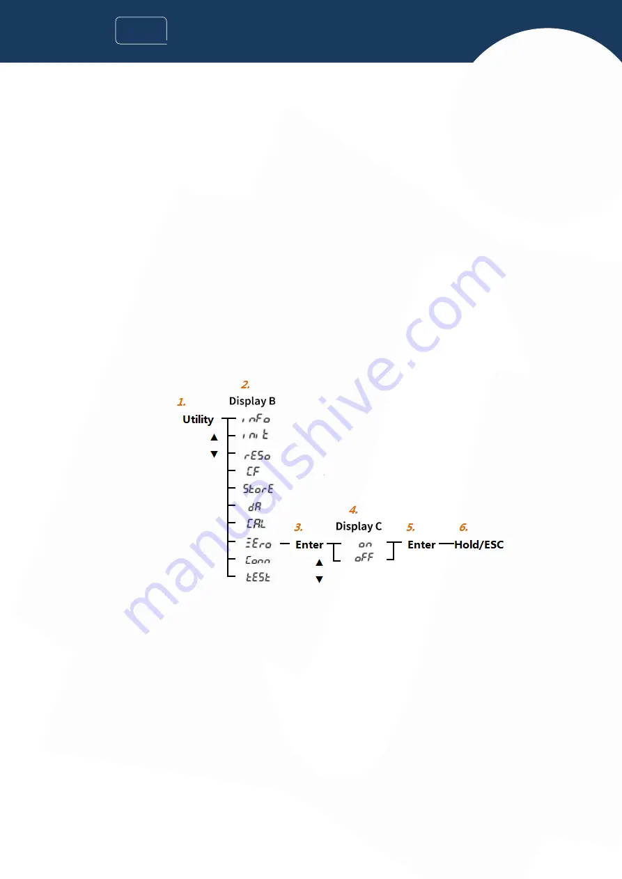
1. Press Utility key;
2. Choose “Zero” setting menu;
3. Confirm;
4. Set zero switch;
5. Confirm;
6. Exit and close the setting menu.
Follow the steps above, zero setting is located at C display column, then zero switch can be switched by navigation keys (UP,
DOWN); press “Enter” key to complete the setting, the instrument returns to the previous menu, and press “Hold/ESC” key
to exit the setting interface.
Function specifications
Zero switch is turned on, and too small voltage and current measurement is displayed
CF=3, measurement ≤ 0.5% of rated range (CF=6, ≤1%):
Voltage, current or other measured values related thereto will be displayed as "0.000" or "0.0000";
The phase angle and power factor will be displayed as "Error";
Zero switch is turned off, zero is not implemented for the measurement, and actual test value is displayed.


