17
LUBRICATION
To ensure continued satisfactory operation of the winch, all
points requiring lubrication must be serviced with the correct
lubricant at the proper time interval as indicated for each
assembly.
The lubrication intervals recommended in this manual are based
on intermittent operation of the winch eight hours each day, five
days per week. If the winch is operated almost continuously or
more than the eight hours each day, more frequent lubrication
will be required. Also, the lubricant types and change intervals
are based on operation in an environment relatively free of dust,
moisture, and corrosive fumes. Use only those lubricants
recommended. Other lubricants may affect the performance of
the winch. Approval for the use of other lubricants must be
obtained from your Ingersoll-Rand distributor. Failure to
observe this precaution may result in damage to the winch and/
or its associated components.
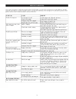
INTERVAL
LUBRICATION CHECKS
Start of each
shift
Check flow and level of air line lubricator
(adjust flow to approximately 6 to 9 drops
per minute at maximum motor speed.).
Check winch motor oil level.
Monthly
Inspect and clean or replace air line filter.
Check reduction gear oil level.
Yearly
Drain and refill winch reduction gear oil.
Drain and refill the oil in the winch motor.
Note: Intervals are based on winch operation in a normal
environment as described in the “INSPECTION” section. In
‘Heavy’ or ‘Severe’ operating conditions adjust lubrication
intervals accordingly.
General Lubrication
1.
Drain and replace oil in the motor, disc brake and reduction
gear after the first 50 hours of initial winch operation.
Thereafter, drain and replace oil according to the intervals
recommended.
2.
Always inspect removed oil for evidence of internal
damage or contamination (metal shavings, dirt, water, etc.).
If indications of damage are noted, investigate and correct
before returning winch to service.
3.
After winch operation, allow oil to settle before topping
off.
4.
Always collect lubricants in suitable containers and dispose
of in an environmentally safe manner.
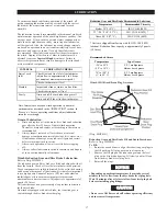
Winch Reduction Gear and Disc Brake Lubrication
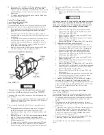
Refer to Dwg. MHP0501.
The reduction gear and disc brake are filled and shipped with oil
from the factory. Check oil level before initial winch operation.
These components are splash lubricated by the oil in the housing
and have no other means of lubrication. It is therefore important
to use high quality Extreme Pressure (EP) rust and oxidation
inhibited gear oils to ensure maximum performance and
minimum down time for repairs. Oil capacity is approximately 3
quarts (2.8 litres).
Oil from the reduction gear assembly also provides lubrication
for the disc brake.
On winches equipped with a disc brake, the reduction gear is
vented through the disc brake breather plug.
Reduction Gear and Disc Brake Recommended Lubricant
Temperature
Recommended Viscosity
Below 32° F (0° C)
ISO VG 68 (20W)
32° - 80° F (0° - 27° C)
ISO VG 100 (30W) *
Above 80° F (27° C)
ISO VG 150 (40W)
* Units are shipped from factory with ISO VG 100 (30W)
lubricant. Reduction Gear capacity is approximately 2 quarts
(1.9 litres).
Recommended Grease
Temperature
Type Grease
-20° to 50° F
(-30° to 10° C)
EP 1 multipurpose
lithium based grease
30° to 120° F
(-1° to 49° C)
EP 2 multipurpose
lithium based grease
(Dwg. MHP0501)
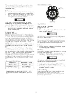
Reduction Gear and Disc Brake Fill and Drain Procedures
Refer to Dwg. MHP0501.
To Fill:
1.
Rotate the winch drum to align the reduction gear plugs to
the fill position. Fill plug position is at top center.
2.
Remove the fill plug on the reduction gear and the level
plug on the disc brake housing. Fill slowly until oil flows
from the disc brake level plug hole.
3.
Reinstall the plugs.
NOTICE
• Depending on ambient temperature it may take several
minutes for oil to flow from the disc brake level plug hole.
Wait 10 minutes after oil starts to flow from level plug hole
before reinstalling plug fittings.
CAUTION
• Do not over fill. Excess oil will reduce operating efficiency
and increase oil temperature.
Summary of Contents for force5 FA5A-LAK1
Page 34: ...34 WINCH ASSEMBLY PARTS DRAWING ...
Page 36: ...36 MOTOR ASSEMBLY PARTS DRAWING ...
Page 38: ...38 DISC BRAKE ASSEMBLY PARTS DRAWING ...
Page 40: ...40 DRUM BAND BRAKE ASSEMBLY PARTS DRAWING ...
Page 42: ...42 LEVER OPERATED CONTROL VALVE ASSEMBLY PARTS DRAWING ...
Page 44: ...44 PENDANT OPERATED PILOT CONTROL VALVE ASSEMBLY PARTS DRAWING ...
Page 48: ...48 SHUTTLE VALVE ASSEMBLY PARTS DRAWING ...
Page 50: ...50 EMERGENCY STOP AND OVERLOAD ASSEMBLY PARTS DRAWING ...
Page 52: ...52 OPEN FRAME FACE WINCH ASSEMBLY PARTS DRAWING ...
Page 57: ...57 WINCH LABEL TAG LOCATION AND PART NUMBER REFERENCE DRAWING ...

