46
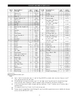
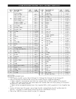
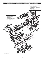
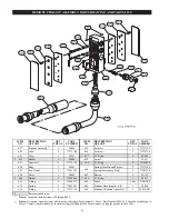
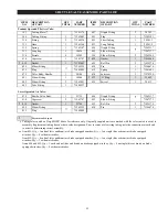
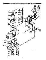
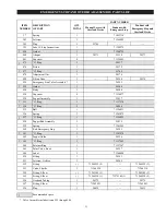
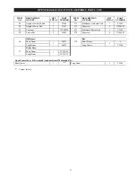
REMOTE PENDANT ASSEMBLY PARTS DRAWING AND PARTS LIST
ITEM
NO.
DESCRIPTION
OF PART
QTY
TOTAL
PART
NUMBER
ITEM
NO.
DESCRIPTION
OF PART
QTY
TOTAL
PART
NUMBER
627
Pendant Assembly *
1
24445
635
Setscrew
3
71273122
620
Label
2
71273106
636
Setscrew
1
71274724
621
Cover
1
24447
•
637
‘O’ Ring
1
52662
•
622
Gasket
2
24444
638
Swivel
1
24433
623
Capscrew
11
71273130
•
639
‘O’ Ring
6
71126825
624
Body
1
24441
640
Spring (Haul-In and Payout)
2
71271142
625
Pin, Dowel
2
71261341
Spring (Emergency Stop)
1
71261390
626
Cover
1
24443
641
Button
3
24155
•
628
Gasket
2
71044960
•
642
‘O’ Ring
3
50557
631
Fitting
2
71044937
643
Label
1 Set
71261309
632
Spring
2
71263081
645
Pendant Hose (length - 6 ft)
1
26028
633
Fitting
2
71273114
646
Pendant Extension Assembly **
1
24259-XX
•
Recommended spare.
*
Pendant Assembly includes items 620 through 645.
**
Pendant Extension Assembly (item 646) must be ordered in feet. Example: 15 feet = Part Number 24259-15. Lengths available up to
54 feet. Contact your distributor or the nearest Ingersoll-Rand office for assistance on lengths greater than 54 feet.
Summary of Contents for force5 FA5A-LAK1
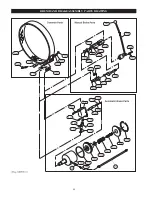
Page 34: ...34 WINCH ASSEMBLY PARTS DRAWING ...
Page 36: ...36 MOTOR ASSEMBLY PARTS DRAWING ...
Page 38: ...38 DISC BRAKE ASSEMBLY PARTS DRAWING ...
Page 40: ...40 DRUM BAND BRAKE ASSEMBLY PARTS DRAWING ...
Page 42: ...42 LEVER OPERATED CONTROL VALVE ASSEMBLY PARTS DRAWING ...
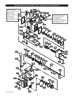
Page 44: ...44 PENDANT OPERATED PILOT CONTROL VALVE ASSEMBLY PARTS DRAWING ...
Page 48: ...48 SHUTTLE VALVE ASSEMBLY PARTS DRAWING ...
Page 50: ...50 EMERGENCY STOP AND OVERLOAD ASSEMBLY PARTS DRAWING ...
Page 52: ...52 OPEN FRAME FACE WINCH ASSEMBLY PARTS DRAWING ...
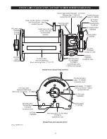
Page 57: ...57 WINCH LABEL TAG LOCATION AND PART NUMBER REFERENCE DRAWING ...

