


29
4.
Slide spring (462) over handle and onto pin.
5.
Insert this assembly up through the bottom of cross shaft
(461). ‘The bottom’ is the side with the groove for locating
pin (463).
6.
Apply a drop of Loctite
®
242 to threads on handle. Install
knob (469) and tighten.
7.
Install detent plate (464) on valve cap (450) with cutout
portion of plate located at bottom. Coat threads with
Loctite
®
680, install and tighten capscrews (465) to 42 - 45
inch lbs (15 - 17 Nm). Install cross shaft (461) without ‘O’
rings. Ensure cross shaft rotates freely. Remove cross shaft.
8.
Place split section of clevis (446) on shaft (401). Ensure
rounded section of clevis is towards the valve body (410)
and is located on top. Coat pin (409) with Loctite
®
609 and
press into lower slot (perpendicular to shaft), through shaft
and into lower slot located on opposite of clevis. Center pin
in clevis.
9.
Place valve body (410) on its side with the clevis end over
the edge of the workbench.
10. Place gasket (411) on valve cap (450) and slide assembly
over clevis. Lubricate threads and loosely install capscrews
(437) and (439) and washers (433).
11. From the bottom hole in valve cap use a punch, or similar
tool, to align the cross shaft holes in valve cap with the hole
in the clevis. Use tool to maintain position and tighten
capscrews to 54 - 60 inch lbs (20 - 22 Nm).
NOTICE
• The slotted pin grooves in the clevis (where clevis and shaft
(401) are joined) make alignment of the cross shaft and clevis
difficult. To prevent binding of cross shaft during
installation, ensure the cross shaft holes (located in valve cap)
and the clevis hole are aligned before installing cross shaft.
12. Lubricate ‘O’ rings (448) and locate in grooves on cross
shaft (461). Insert cross shaft through detent plate side of
valve cap assembly. To complete, raise handle assembly up
and insert pin (463) into detent plate while pushing on
cross shaft.
13. Align the hole in the cross shaft with the hole in the end of
the clevis. Apply a bead of Loctite
®
242 to pin (445).
Using an 8-32 x 2 inch screw attached to the threaded end
of pin, install pin by tapping into position. Ensure pin is
inserted fully into clevis.
14. Operate the lever in both directions. There should be no
indication of sticking or binding. When released, the lever
must return to the neutral position and lock in place (handle
must be lifted before shifting in either direction).
15. Coat threads of plug (447) with pipe sealant and install in
valve cap end.
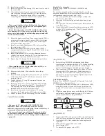
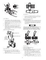
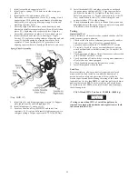
Valve Cap Assembly
Refer to Dwg. MHP0654.
The following describes the assembly of the valve cap assembly
located on the end opposite the lever control handle.
1.
Install washers (434) on shaft (401). Place enough on shaft
to establish an 0.06 - 0.12 inch (1.5 - 3.0 mm) clearance
between the interior washer face and the poppet assembly
(423) end face. Secure in place with cotter pin (414) with
ends bent back to hold in place.
2.
Lubricate threads and install capscrews (437) and (439),
washers (433), gasket (411) and valve cap (438) to valve
body (410). Tighten capscrews to 54 - 60 inch lbs (20 - 22
Nm).
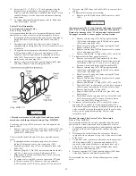
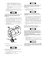
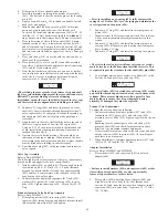
Pendant Operated Valve End Cap Assembly
Refer to Dwg. MHP0653.
1.
Slide spring retainer (459) into spring (452). Insert
capscrew (465) through spring end and into retainer. Install
this assembly into piston (454) and tighten.
NOTICE
• Prior to installing a new spring (452), fully compress the
spring 10 to 12 times. This ‘sets’ the spring and maintains the
correct preload on the piston (454).
2.
Lubricate ‘O’ ring (453) and install in external groove on
piston (454).
3.
Install setscrew (458) into piston until flush. This setscrew
will be used to complete valve adjustments later in this
section.
4.
Lubricate ‘O’ ring (455) and install in internal groove in
seal cup (456). Slide seal cup onto piston shaft taking care
not to dislodge ‘O’ ring.
5.
Lubricate ‘O’ ring (457) and install in seal cup face groove.
NOTICE
• The slot in the seal cup (viewed from valve cap cover end)
must be located at the bottom when installed correctly. This
is required to provide clearance for the shaft (401) pins (406).
6.
Coat external mating sleeve surface of cylinder (451) with
Loctite
®
609 and press into valve cap (438).
CAUTION
• Ensure cylinder (451) is pressed into valve cap (438) evenly
and with the threaded port located at the exact bottom of the
cylinder. These are machined parts with a press fit. Care
must be taken to ensure they are not damaged during
assembly. If damaged they must be replaced.
Pendant Valve Adjustment
To adjust the valve conduct the following:
1.
Lubricate threads and install capscrews (437) and (439),
lockwashers (433), gasket (411) and valve cap (438)
assembly to valve body (410). Tighten capscrew, but do not
torque.
2.
Reaching into the exhaust port on the valve body (410)
grasp the shaft (401) and check for movement in either
direction. Any movement requires adjustment.
3.
If there is shaft movement, remove the valve caps and back
out the setscrews (458) in pistons (454) 1/4 turn. Repeat
until there is no movement.
4.
When adjustment is complete tighten capscrews (437) and
(439) to 54 - 60 inch lbs (20 - 22 Nm).
Adapter Installation
Refer to Dwgs. MHP0653 and MHP0654.
1.
Place washers (434) and capscrews (442) in holes in
adapter (440).
NOTICE
• Failure to install washers (434) and capscrews (442) at this
time will require adapter (440) or valve cap assembly
removal to provide access to these holes.
2.
Place gasket (424) on mating face of adapter (440) and
align holes with valve body (410). Coat threads with
Loctite
®
242 and, from the bottom side of adapter, install
capscrews (441) into valve body. Tighten to 13 - 17 ft lbs
(58 - 76 Nm).
Summary of Contents for force5 FA5A-LAK1
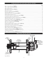
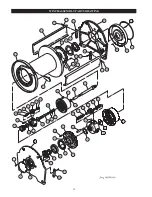
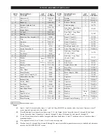
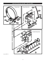
Page 34: ...34 WINCH ASSEMBLY PARTS DRAWING ...
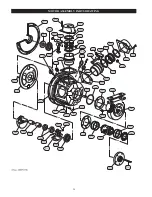
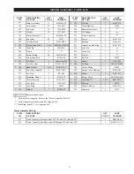
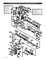
Page 36: ...36 MOTOR ASSEMBLY PARTS DRAWING ...
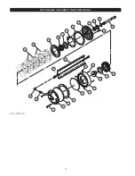
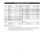
Page 38: ...38 DISC BRAKE ASSEMBLY PARTS DRAWING ...
Page 40: ...40 DRUM BAND BRAKE ASSEMBLY PARTS DRAWING ...
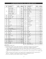
Page 42: ...42 LEVER OPERATED CONTROL VALVE ASSEMBLY PARTS DRAWING ...
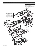
Page 44: ...44 PENDANT OPERATED PILOT CONTROL VALVE ASSEMBLY PARTS DRAWING ...
Page 48: ...48 SHUTTLE VALVE ASSEMBLY PARTS DRAWING ...
Page 50: ...50 EMERGENCY STOP AND OVERLOAD ASSEMBLY PARTS DRAWING ...
Page 52: ...52 OPEN FRAME FACE WINCH ASSEMBLY PARTS DRAWING ...
Page 57: ...57 WINCH LABEL TAG LOCATION AND PART NUMBER REFERENCE DRAWING ...


