58
Return Goods Policy
Ingersoll-Rand will not accept any returned goods for warranty
or service work unless prior arrangements have been made and
written authorization has been provided from the location where
the goods were purchased.
Winches which have been modified without Ingersoll-Rand
approval, mishandled or overloaded will not be repaired or
replaced under warranty. A printed copy of the warranty which
applies to this winch is provided inside the back cover of this
manual.
Disposal
When the life of the unit has expired, it is recommended that it
be disassembled, degreased and parts separated as to materials
so that they may be recycled.
For additional information contact:
Ingersoll-Rand Material Handling
P.O. Box 24046
2724 Sixth Avenue South
Seattle, WA 98124-0046 USA
Phone:
(206) 624-0466
Fax:
(206) 624-6265
or
Ingersoll-Rand Material Handling
Douai Operations
111, avenue Roger Salengro
59450 Sin Le Noble, France
Phone:
(33) 3-27-93-08-08
Fax:
(33) 3-27-93-08-00
PARTS ORDERING INFORMATION
The use of other than Ingersoll-Rand Material Handling
replacement parts may adversely affect the safe operation and
performance of this product.
For your convenience and future reference it is recommended
that the following information be recorded.
Model Number
Serial Number
Date Purchased
When ordering replacement parts, please specify the following:
1.
Complete model number and serial number as it appears on
the nameplate.
2.
Part number(s) and part description as shown in this
manual.
3.
Quantity required.
The nameplate is located on the winch outboard upright.
NOTICE
• Continuing improvement and advancement of design may
cause changes to this equipment which are not included in
this manual. Manuals are periodically revised to incorporate
changes. Always check the manual edition number on the
front cover for the latest issue.
• Sections of this manual may not apply to your winch.
Summary of Contents for force5 FA5A-LAK1
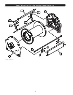
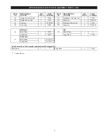
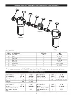
Page 34: ...34 WINCH ASSEMBLY PARTS DRAWING ...
Page 36: ...36 MOTOR ASSEMBLY PARTS DRAWING ...
Page 38: ...38 DISC BRAKE ASSEMBLY PARTS DRAWING ...
Page 40: ...40 DRUM BAND BRAKE ASSEMBLY PARTS DRAWING ...
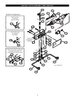
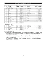
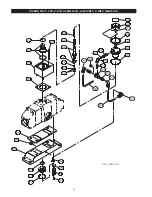
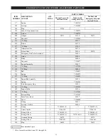
Page 42: ...42 LEVER OPERATED CONTROL VALVE ASSEMBLY PARTS DRAWING ...
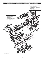
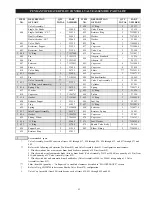
Page 44: ...44 PENDANT OPERATED PILOT CONTROL VALVE ASSEMBLY PARTS DRAWING ...
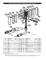
Page 48: ...48 SHUTTLE VALVE ASSEMBLY PARTS DRAWING ...
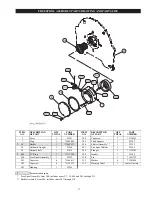
Page 50: ...50 EMERGENCY STOP AND OVERLOAD ASSEMBLY PARTS DRAWING ...
Page 52: ...52 OPEN FRAME FACE WINCH ASSEMBLY PARTS DRAWING ...
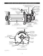
Page 57: ...57 WINCH LABEL TAG LOCATION AND PART NUMBER REFERENCE DRAWING ...

