10
Motor
For optimum performance and maximum durability of parts,
provide an air supply of 600 scfm (17 cu. m/m) at 90 psig (6.3
bar/630 kPa). The air motor should be installed as near as
possible to the compressor or air receiver. Recommended
pressures and volumes are measured at the point of entry to the
air motor directional control valve.
Initial Winch Operating Checks
Winches are tested for proper operation prior to leaving the
factory. Before the winch is placed into service the following
initial operating checks should be performed.
1.
When first running the motor inject some light oil into the
inlet connection to provide initial lubrication.
2.
When first operating the winch it is recommended that the
motor be driven slowly in both directions for a few
minutes.
For winches that have been in storage the following start-up
procedures are required.
1.
Give the winch an inspection conforming to the
requirements of "Winches Not in Regular Use" in the
"INSPECTION" section.
2.
Pour a small amount of ISO VG 32 (10W) lubricant in the
motor inlet port.
3.
Operate the motor for 10 seconds in both directions to flush
out any impurities.
4.
Check to ensure oil levels are “full”.
5.
The winch is now ready for normal use.
OPERATION
The four most important aspects of winch operation are:
1.
Follow all safety instructions when operating the winch.
2.
Allow only people trained in safety and operation of this
winch to operate this equipment.
3.
Subject each winch to a regular inspection and maintenance
procedure.
4.
Be aware of the winch capacity and weight of load at all
times.
CAUTION
• To avoid damage to the rigging, the structure supporting
the rigging and the winch, do not "two-block*" the end of
the wire rope.
* Two blocking occurs when the winch wire rope is multi reeved
using two separate sheave blocks which are allowed to come
into contact with each other during winch operation. When this
occurs extreme forces are exerted on the wire rope and sheave
blocks which may result in equipment and or rigging failure.
WARNING
• The winch is not designed or suitable for lifting, lowering or
moving people. Never lift loads over people.
Operators must be physically competent. Operators must have
no health condition which might affect their ability to act, and
they must have good hearing, vision and depth perception. The
winch operator must be carefully instructed in his duties and
must understand the operation of the winch, including a study of
the manufacturer’s literature. The operator must thoroughly
understand proper methods of hitching loads and should have a
good attitude regarding safety. It is the operator’s responsibility
to refuse to operate the winch under unsafe conditions.
Winch Controls
A spring loaded, motor mounted, manual throttle control valve
is supplied as a standard feature on these winches. Optional
remote throttle controls are also available. Reference the model
code on the winch nameplate and compare it to the
"SPECIFICATIONS" section of this manual to determine your
configuration. The throttle control provides operator control of
the motor speed and direction of drum rotation.
Operate winch throttle control using smooth, even movements.
Do not slam or jerk throttle controls during operation.
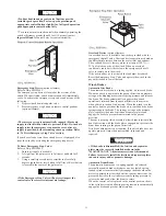
Winch Mounted Air Throttle (standard feature)
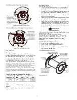
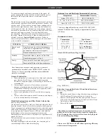
Refer to Dwg. MHP0699.
The winch mounted throttle lever prevents accidental operation
by locking in the neutral position when released. To operate, the
control throttle handle must be lifted up prior to being shifted in
the desired direction. To control winch direction move the
control throttle handle, as viewed from the motor end, to the
right (clockwise) to payout wire rope and to the left
(counterclockwise) to haul-in wire rope.
The throttle lever will return to the neutral (off) position when
the lever is released.
(Dwg. MHP0699)
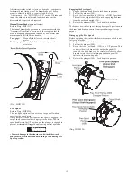
Remote Control Pendant (optional feature)
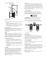
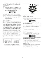
Refer to Dwg. MHP0696.
Provides for remote winch control at distances up to 60* feet (18
metres) away from the winch motor. Pilot air hoses connect the
pendant to the winch motor to provide winch operation. The
pendant control is a three button movable control station which
controls payout, haul-in and is equipped with an emergency
shut-off. Direction of winch drum rotation is determined by
direction of air flow into the pilot valve. Labels on the pendant
buttons indicate winch operation.
Depress pendant buttons using smooth, even movements.
Summary of Contents for force5 FA5A-LAK1
Page 34: ...34 WINCH ASSEMBLY PARTS DRAWING ...
Page 36: ...36 MOTOR ASSEMBLY PARTS DRAWING ...
Page 38: ...38 DISC BRAKE ASSEMBLY PARTS DRAWING ...
Page 40: ...40 DRUM BAND BRAKE ASSEMBLY PARTS DRAWING ...
Page 42: ...42 LEVER OPERATED CONTROL VALVE ASSEMBLY PARTS DRAWING ...
Page 44: ...44 PENDANT OPERATED PILOT CONTROL VALVE ASSEMBLY PARTS DRAWING ...
Page 48: ...48 SHUTTLE VALVE ASSEMBLY PARTS DRAWING ...
Page 50: ...50 EMERGENCY STOP AND OVERLOAD ASSEMBLY PARTS DRAWING ...
Page 52: ...52 OPEN FRAME FACE WINCH ASSEMBLY PARTS DRAWING ...
Page 57: ...57 WINCH LABEL TAG LOCATION AND PART NUMBER REFERENCE DRAWING ...


