


11
NOTICE
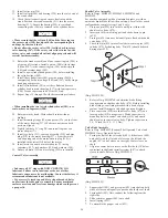
• Pendant haul-in and payout control buttons provide
variable speed operation. For low speed operation push
appropriate control button slightly; for full speed operation
push appropriate control button fully.
* To ensure accurate winch control when remotely operating the
winch at distances greater than 60 feet (18 metres) contact
Ingersoll-Rand Technical Sales for control suitability.
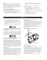
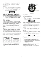
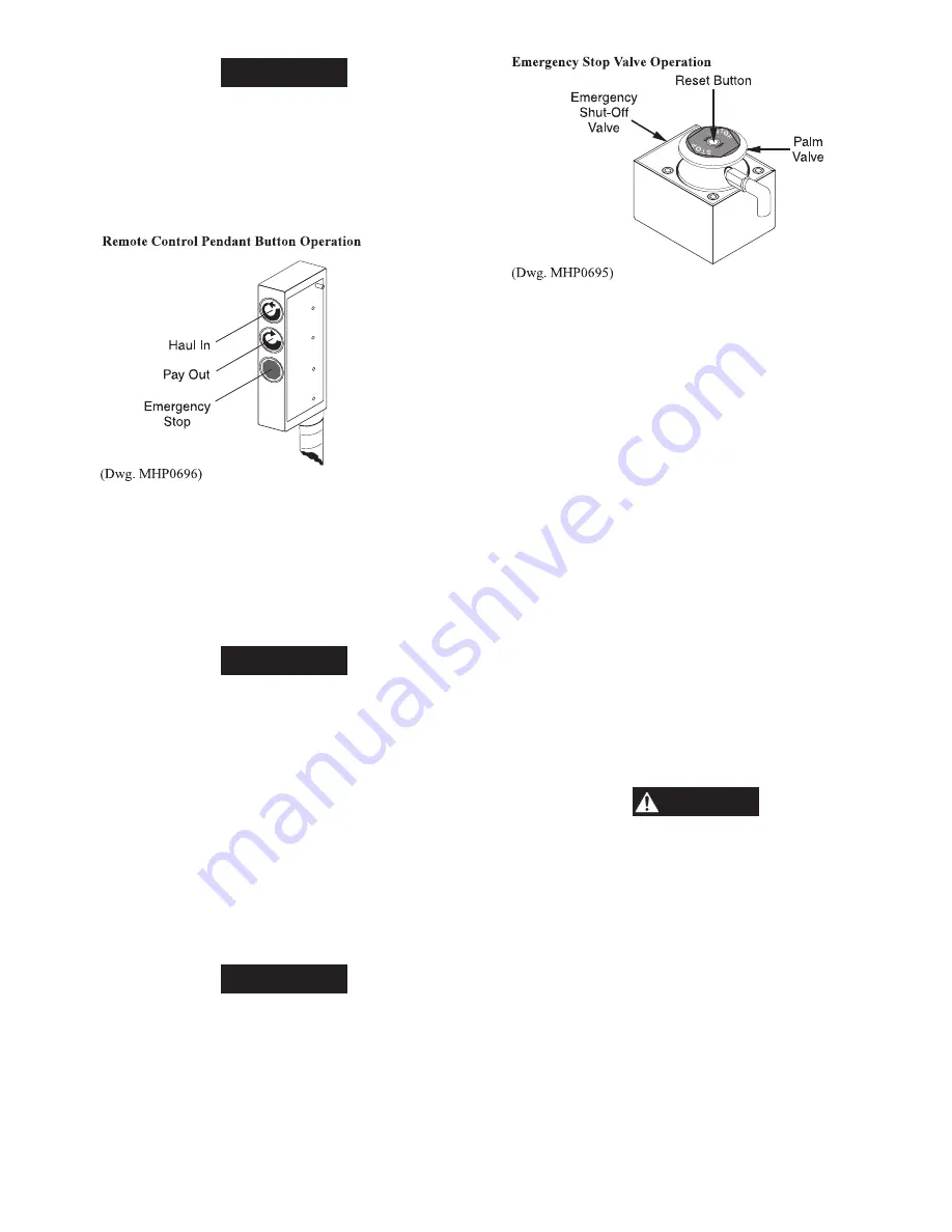
Emergency Stop Device (optional feature)
Refer to Dwg. MHP0695.
The emergency stop device is located at the air inlet of the
winch. When activated, winch drum rotation will immediately
cease. To activate the emergency stop valve conduct one of the
following:
1.
Depress (push down) red palm valve.
2.
Press emergency stop button on remote control pendant
(optional feature).
NOTICE
• The emergency stop is automatically engaged (blocks air
supply to winch) when winch air pressure is lost. If winch air
supply is lost the emergency stop must be reset, after air
supply is provided, before resuming winch operation. Refer
to ‘To Reset Emergency Stop Valve’ section.
If winch overload occurs the overload device, if equipped, also
stops the winch by activating the emergency stop device.
To Reset Emergency Stop Valve:
Refer to Dwg. MHP0695.
1.
Ensure air supply is available.
2.
Lift (pull up) red palm valve to full travel and hold for 2
seconds.
3.
Using a small tip screwdriver or similar tool, carefully
depress (push down) reset button to full travel. Reset button
is located in the center of the palm valve.
NOTICE
• If the Emergency Stop Valve will not reset inspect the
control valve for excessive internal air leakage.
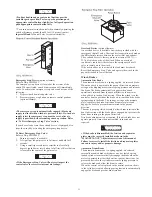
Overload Device (optional feature)
An overload device is available on winches provided with the
emergency shut-off valve. Overload device operation is based on
the differential pressure between the motor inlet and exhaust.
The overload device is factory preset to actuate at 150% (+/-
25%) of rated capacity of the winch. When an overload
condition is sensed air is directed to the emergency shut-off
valve to isolate air to the winch.
If the overload device is activated the load must be reduced.
Reset the Emergency Stop Valve and operate the winch in the
payout direction to lower the load.
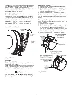
Winch Brakes
Automatic Disc Brake
The automatic disc brake is a spring applied, air released brake.
When the winch is operated in the payout direction air pressure
acting on the diaphragm overcomes spring pressure and releases
the brake. The brake automatically engages when winch
operation is returned from the payout direction to neutral or
when shifted to the haul-in direction. When the winch is in the
neutral or haul-in positions the brake air is vented and the brake
springs reapply the brake. The springs, acting on the pressure
plate, compress the brake friction and separator plates and
engage the brake to prevent drum rotation in the payout
direction.
The cam type sprag clutch assembly allows drum rotation in the
haul-in direction with the brake plates engaged, but prevents the
drum from rotating in the payout direction.
Disc brake adjustment is not required. If the disc brake does not
operate properly it must be disassembled, inspected and
repaired.
WARNING
• If the brake is disassembled, the friction and separator
plates must be correctly installed as shown in the
“MAINTENANCE” Adjustments section of this manual.
Failure to correctly install the friction and separator plates
can cause injury and/or property damage.
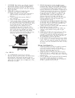
Automatic Drum Brake
The automatic drum brake is a spring applied, air released,
externally mounted brake which uses an air actuated, spring
loaded cylinder to automatically disengage the brake when the
motor is operated in either the haul-in or payout directions. Air
pressure directed to the cylinder overcomes spring pressure to
release the brake and allow the drum to rotate.
When the control valve is placed in the neutral position, the air
in the cylinder is vented allowing spring tension to automatically
engage the brake and prevent drum rotation.
Summary of Contents for force5 FA5A-LAK1
Page 34: ...34 WINCH ASSEMBLY PARTS DRAWING ...
Page 36: ...36 MOTOR ASSEMBLY PARTS DRAWING ...
Page 38: ...38 DISC BRAKE ASSEMBLY PARTS DRAWING ...
Page 40: ...40 DRUM BAND BRAKE ASSEMBLY PARTS DRAWING ...
Page 42: ...42 LEVER OPERATED CONTROL VALVE ASSEMBLY PARTS DRAWING ...
Page 44: ...44 PENDANT OPERATED PILOT CONTROL VALVE ASSEMBLY PARTS DRAWING ...
Page 48: ...48 SHUTTLE VALVE ASSEMBLY PARTS DRAWING ...
Page 50: ...50 EMERGENCY STOP AND OVERLOAD ASSEMBLY PARTS DRAWING ...
Page 52: ...52 OPEN FRAME FACE WINCH ASSEMBLY PARTS DRAWING ...
Page 57: ...57 WINCH LABEL TAG LOCATION AND PART NUMBER REFERENCE DRAWING ...


