
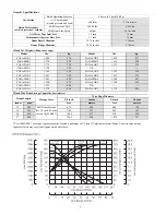


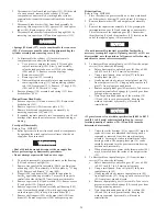
12
Adjustments to the cylinder clevis can be made to compensate
for normal brake lining wear. The drum brake must be kept
properly adjusted to hold the required load. Refer to
‘Adjustments’ in the “MAINTENANCE” section. If brake band
cannot be adjusted to hold rated load, the brake must be
disassembled, inspected and repaired.
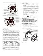
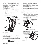
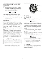
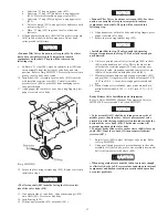
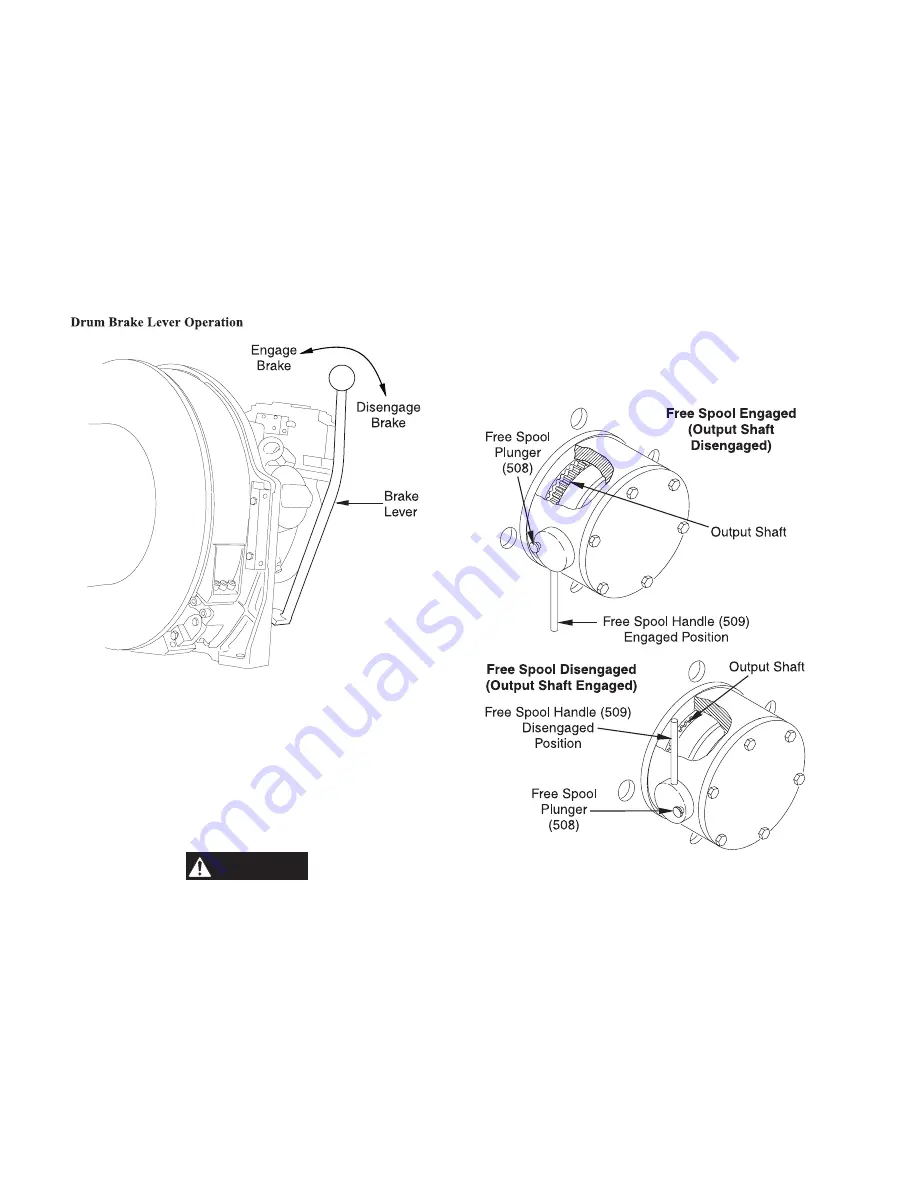
Manual Drum Brake (optional feature)
Refer to Dwg. MHP1212.
The manual drum brake operation is the same as described in
“Automatic Drum Brake” section with the exception that the
brake is manually engaged and released by an operator who
must manually shift the brake handle.
To engage:
Manually shift lever in, towards the air
motor.
To disengage: Manually shift lever out, away from the
air motor.
(Dwg. MHP1212)
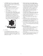
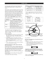
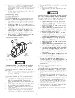
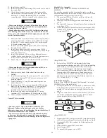
Free Spool
Refer to Dwg. MHP0926.
The Free Spool option allows wire rope to spool off without
operating the winch motor.
During normal winch operations the free spool is engaged. The
output shaft connects outboard upright to the drum. The free
spool handle is in the UP position and the plunger is engaged to
prevent accidental shifting of handle during normal operation.
WARNING
• To avoid damage to the structure and winch the winch
drum must be stationary and not holding a load during Free
Spool operation.
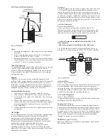
Engaging the Free Spool:
1.
Engage the drum band brake to lock drum in position.
2.
Pull out the plunger (508).
3.
Rotate the free-spool handle (509) to the DOWN position.
This pulls the output shaft (28) out, disengaging the drum
from the outboard upright (26).
4.
Release the plunger (508) to lock handle in position.
The drum is now in free spool. During free spool operations use
the drum band brake to control drum speed during wire rope
payout.
Disengaging the Free Spool:
Before operating the winch with the motor, ensure winch is not
in free spool mode.
1.
Engage the drum band brake.
2.
Pull out the plunger (508).
3.
Rotate the free spool handle (509) to the UP position. This
connects the winch drum to the outboard upright. If
required, the band brake can be carefully released to allow
drum to rotate to assist in lining up outboard gear (28)
splines with drum and upright.
4.
Release the plunger (508) to lock handle in position.
(Dwg. MHP0926)
Summary of Contents for force5 FA5A-LAK1
Page 34: ...34 WINCH ASSEMBLY PARTS DRAWING ...
Page 36: ...36 MOTOR ASSEMBLY PARTS DRAWING ...
Page 38: ...38 DISC BRAKE ASSEMBLY PARTS DRAWING ...
Page 40: ...40 DRUM BAND BRAKE ASSEMBLY PARTS DRAWING ...
Page 42: ...42 LEVER OPERATED CONTROL VALVE ASSEMBLY PARTS DRAWING ...
Page 44: ...44 PENDANT OPERATED PILOT CONTROL VALVE ASSEMBLY PARTS DRAWING ...
Page 48: ...48 SHUTTLE VALVE ASSEMBLY PARTS DRAWING ...
Page 50: ...50 EMERGENCY STOP AND OVERLOAD ASSEMBLY PARTS DRAWING ...
Page 52: ...52 OPEN FRAME FACE WINCH ASSEMBLY PARTS DRAWING ...
Page 57: ...57 WINCH LABEL TAG LOCATION AND PART NUMBER REFERENCE DRAWING ...


