Everest XCR - Product Manual |
Wiring and Connections
INGENIA | 08/04/2019
45
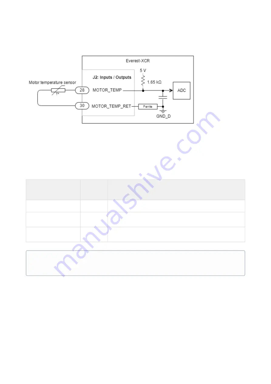
temperature. The motion controller includes linearization for various sensors so the motor temperature can be
read directly.
9.5. Feedbacks
The Everest XCR can be connected
to
a maximum of 3 feedback devices at the same time that might be used for
commutation and/or velocity/position control purposes. These devices are connected in the J1 connector of the
board in with the following pin definitions:
Feedback port
J1
connector
pins
Allowed feedbacks
Digital Halls
9 to 13
Digital Halls, open collector or push-pull.
Absolute encoder 1
14 to 19
SSI absolute encoder, Single BISS-C, Dual BiSS-C in daisy chain
topology (up to 2)
Incremental encoder /
Absolute encoder 2
1 to 8
Quadrature incremental encoder (S0S90), SSI absolute encoder.
9.5.1. Digital Halls
The Hall sensors are Hall effect devices that are built into the motor to detect the position of the rotor magnetic
field. Usually, motors include 3 Hall sensors, spaced 120º (electrical degrees) apart that are in phase with the stator
position. Using these 3 signals, the drive is capable to detect the position, direction and velocity of the rotor. The
Halls
effect sensors are a good way to detect the phasing of the motor and avoid "
wake and shake"
movements. Everest XCR can use digital Hall sensors alone to drive the motor with trapezoidal commutation, but
GND connection required
5 V overcurrent-protected output is provided to power external circuits, including feedback sensors. If it is
not used, and the sensor is powered externally, always remember to connect the ground or reference
voltage to the Everest XCR.


