59
XtrapulsCD1-a
Chapter 8 - Appendix
14 - DRIVE ADDRESSING VIA RS-422
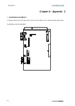
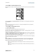
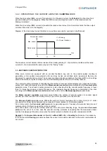
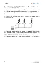
The XtrapulsCD1-a drives allow a multi-axis connection with a host PC via the RS-422 serial link according to the
following connection diagram.
All drives are parallel connected to the computer.
- The drives reception signals (RxD) are connected to the computer transmission signal (TxD).
- The drives transmission signals (TxD) are connected to the computer reception signal (RxD).
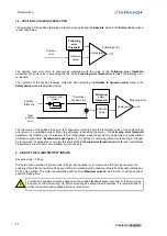
Each XtrapulsCD1a drive has 4 micro-switches allowing an address assignment. The XtrapulsCD1a drives
connected to the computer must have different addresses. An address in multi-axis configuration must have a
value between 1 and 15. The 0 address corresponds to the single-axis communication configuration (no
addressing).
The connection with an drive with address "X" is made by selecting the drive address "X" in the
Setup
menu of
the
VDSetup software
.
15 - COGGING TORQUE COMPENSATION
The cogging torque in brushless permanent magnet rotary motors or the cogging force in brushless permanent
magnet linear motors result from the interaction between the rotor magnets and the stator slots. This disturbance
is due to the difference of reluctance between the copper of the windings and the iron of the stator teeth. For a
given motor, the cogging can be easily evaluated by simply moving the motor manually when the drive is disabled.
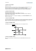
The
Cogging compensation
option available in the Xtrapuls CD1 drive range cancels the motor cogging effects
for specific applications where torque accuracy or force accuracy higher than 1 % are required.
Xtrapuls CD1 drives must get the factory set cogging compensation option (reference CD1a-U/I
–CT). Check for
the presence of the cogging compensation option (
CT-CD1
) in the VDSetup Hardware option menu. In this case,
the
Cogging torque compensation
menu can be selected in the
Servo loop
module.
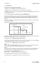
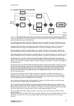
The cogging torque acquisition procedure is started by means of the
Start
button. The motor must be uncoupled
from its load and the shaft must not be disturbed during the procedure. Before starting the acquisition, switch the
drive on manual mode and then disable it (Drive control = Off). Then, start the
Auto-tuning
procedure with
following selections: Regulator = PI², filter = Max. stiffness and bandwidth = High. At the end of the cogging torque
acquisition procedure, the drive parameter file (*.
PAR
) can be uploaded again in order to recover the initial
adjustments.
The
Enable cogging torque compensation
function allows the commissioning of the motor cogging torque
compensation. This function is saved in the drive EEPROM.
The
Save cogging torque data into a file
function allows saving in a PC the cogging torque value corresponding
to a motor after the acquisition procedure (*.
COG
file).
The
Write cogging torque data into the drive
function allows the upload in the drive of he cogging torque value
corresponding to a motor, if this value has previously been stored in the PC (*.
COG
file).
For a brushless motor equipped with an incremental encoder, the Cogging torque compensation is
only available if the encoder is providing one marker pulse per motor revolution.
!
For a brushless motor equipped with an incremental encoder, at the drive power up the cogging
torque compensation is only effective after the detection of the first encoder marker pulse.
!

