38
Chapter 6
– Commissioning
XtrapulsCD1-a
Chapter 6
– Commissioning
1 - DRIVE STANDARD CONFIGURATION
The
XtrapulsCD1-a
drive hardware configuration is made for MAVILOR motors.
Resolver ratio: 0.5.
See Chapter 8, parts 2, 3 and 4 for the drive adjustment to other motor or resolver types.
2 - FIRST POWERING OF THE XTRAPULS CD1-a DRIVE
2.1 - VERY IMPORTANT
Check the connections, particularly of the 24 V
DC
and power supplies. There are two different drive voltage
versions: 230 V
AC
and 400 V
AC
. Check for the appropriate label on the drive. It must be in accordance with the
power connections.
The 400 VAC connection of a 230 V drive will destroy it.
Check for the braking resistor sizing:
- dp 100/100 for 230 VAC
- dp 200/100 for 400 VAC and current ratings 1.8 to 7.2
- dp 50/200 for 14 A current rating
- dp 33/280 for 30 and 45 current ratings
- dp 16.5/560 for 70 and 90 A current ratings.
The ENABLE signal (X2 connector, pin 20) must be disabled and the CV analog command input (X2 connector,
pins 16/17) must be short-circuited.
Check for the correct groundings and 360° shield connections.
2.2 - SWITCH ON THE 24 VDC SUPPLY
The green front panel "ON" Led must light up.
The “Undervolt.” fault must be displayed.
The "AOK" relay contact (pins 18 and 19 of X2) is closed. It is then possible to control the power relay according
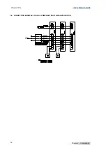
to the recommendations of Chapter 4, section 1: Connection diagrams.
Connection according to X8 sticker.
2.3
– SWITCH ON THE 230 VAC OR 400 VAC SUPPLY (according to the drive type).
Use the power supplies connection drawing while taking into account the AOK relay signal.
The red "UNDERVOLT." LED must go out after a few seconds.
The drive is ready for commissioning by means of the
VISUAL DRIVE SETUP
software (see next section).
The drive must be switched on in following order:
- 24 V supply on
- AOK relay contact closing
- Power on
Otherwise, it may cause physical and material damage.
.
WARNING
During the machine adjustments, some drive connection or parameter setting errors may
involve dangerous axis movements. It is the user's responsibility to take all necessary steps
in order to reduce the risk due to uncontrolled axis movements during the operators'
presence in the concerned area.
!
WARNING
It is mandatory to wait for at least 30 seconds between switching off and on again the drive
!

