background image

Configuring Instruments 


DS2 Docking Station


216 

INDUSTRIAL SCIENTIFIC


Version 9.1 (P/N:  17112798) 


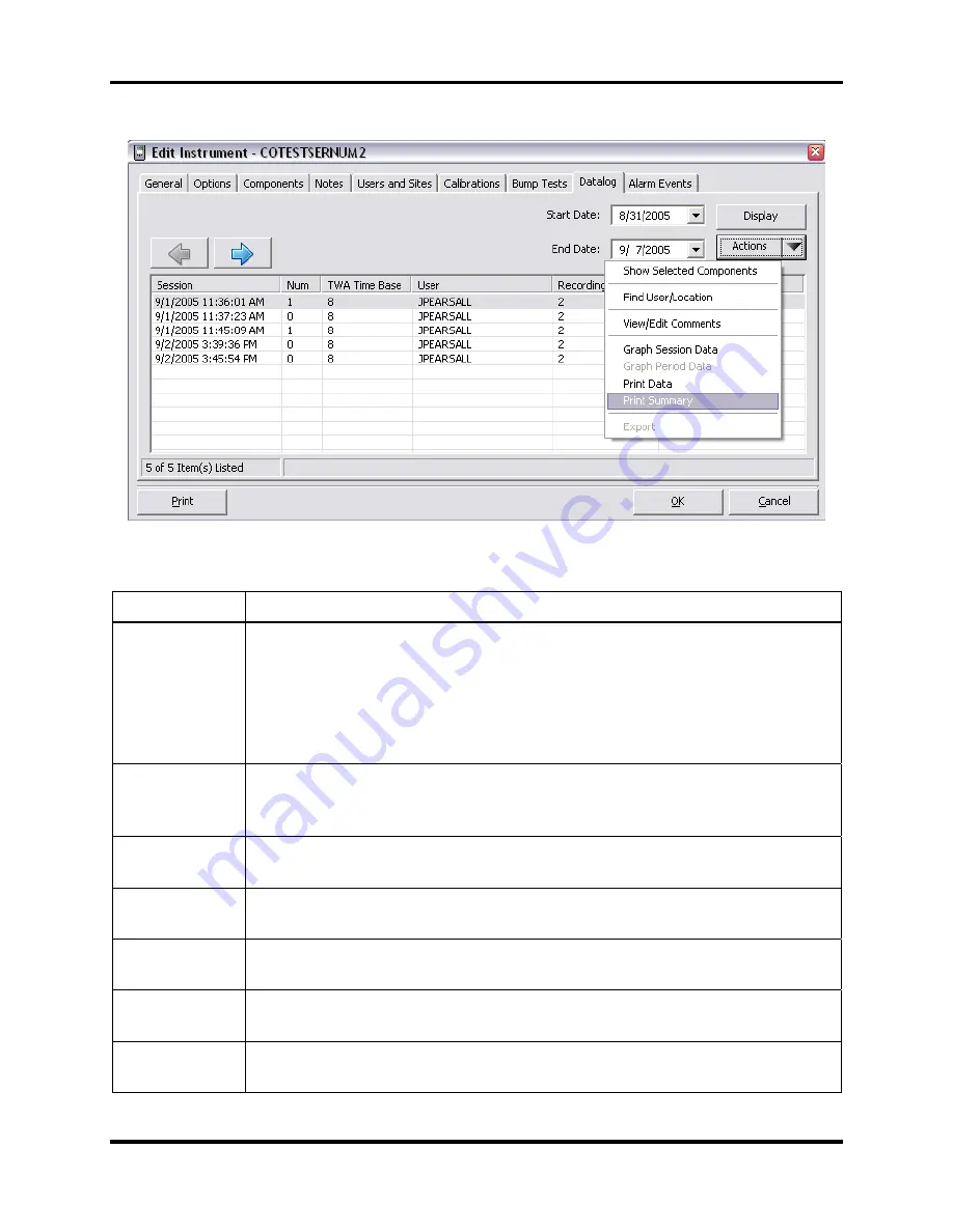
Figure 5-33.  Actions Context Menu 

Table 5-12.  Elements of the Actions Context Menu 

Item Description 

Show Selected 
Components 

Causes the sessions window to change to the session details window.  If the 
datalog data has a session number, this number appears above the session 
date as shown in Figure 5-32. 

Selecting one or more sensors will enable this option on the context menu.  
Selecting this option or double-clicking on any single selection will display 
the Session/Data screen. 

Find 
User/Location 

Presents the user with the Find form which is used to filter session data by 
user, location, and date.  For additional information, refer to the Find 
User/Location section that follows. 

View/Edit 
Comments 

Displays a form in which comments for the selected session can be viewed, 
entered and/or edited.  It is disabled until a session is selected. 

Graph Session 
Data 

Presents a graph of the selected session’s data.  The graph displays data from 
all of the sensors in the session. 

Graph Period 
Data 

Presents a graph of the selected period’s data.  The graph displays data from 
all of the periods in the session.


Print Data 

Prints a Detail Report of the selected session data.  This option is disabled 
until a session is selected. 

Print Summary  Prints a Datalog Summary Report of the selected session data.  This option is 

disabled until a session is selected. 

Summary of Contents for DS2 Docking Station

Page 1: ...Administrator s Guide to the DS2 Docking Station Hardware Software Installation Operation Troubleshooting Part Number 17112798 Release Date December 20 2013 Version No 4...

Page 2: ...r respective owners Industrial Scientific Corporation Phone 412 788 4353 1001 Oakdale Road Toll Free 1 800 DETECTS 338 3287 Oakdale PA 15071 1500 Fax 412 788 8353 USA Service 1 888 788 4353 Although e...

Page 3: ...voltage sags and etc NOTE This product has been tested to and passes all EMC requirements to EN 61326 1998 Electrical Equipment for Measurement Control and Laboratory Use for Type 2 Industrial Appara...

Page 4: ...ystems for detecting measuring and monitoring a wide variety of gases including toxic and combustible gases as well as oxygen From research and development through final manufacturing we never forget...

Page 5: ...nings 15 3 3 Installing Microsoft Internet Information Services IIS and Microsoft Message Queuing MSMQ 17 3 3 1 Overview 17 3 3 2 Installing IIS and MSMQ on Windows 2000 Professional and Windows XP Pr...

Page 6: ...Navigation Pane 81 3 15 6 Using the Contents Pane 82 3 15 7 Viewing and Re instating Removed Instruments 83 3 15 8 The Instrument Node in the Tree View 85 3 15 9 The Profiles Node in the Tree View 86...

Page 7: ...Data 220 5 14 5 Print Summary 222 5 14 6 Export 223 5 15 Edit Instrument Alarm Events Tab 224 5 16 Edit Instrument Manage Events Tab 225 5 17 Special Features 227 5 17 1 Adding Legacy Instruments 227...

Page 8: ...4 Removing a Cluster 213 Event Scheduling 214 9 1 Introduction 214 9 2 Global Events 215 9 2 1 Global Instrument Docking Station Events 215 9 2 2 Global Instrument Events 217 9 3 Special Events 221 9...

Page 9: ...ing the Event Log 248 14 3 DSSAC Issues 251 14 4 DSS Issues 252 14 5 Instrument Docking Station Issues 253 14 6 Enabling the Tracelog 256 14 7 Industrial Scientific Support Services 258 Warranty 259 1...

Page 10: ......

Page 11: ...able this feature Finally an overview of the DSSAC application is provided Chapter 4 Setting Up Users This section explains how to set up user accounts Chapter 5 Configuring Instruments This section p...

Page 12: ...rranty Refer to this section for warranty and liability information Chapter 16 iNet Configuration for the DS2 This section provides an overview of iNet and explains how to configure iNet settings on t...

Page 13: ...dustrial Scientific instruments Tango TX1 Single Gas Monitor Ventis LS Multi Gas Monitor Ventis MX4 Multi Gas Monitor MX4 iQuad Multi Gas Monitor GasBadge Plus GasBadge Pro MX6 iBrid Multi Gas Monitor...

Page 14: ...ent data in a central database Option to use the Industrial Scientific supplied run time database or the customer s own existing Microsoft SQL Server Option to implement Industrial Scientific Corporat...

Page 15: ...g Station Server Admin Console DSSAC is a Windows based application that is used to manage the DS2 Docking Station system The DSSAC is used to manage instrument data view IDS status and manage Docking...

Page 16: ...e batteries An IDS contains an LCD panel that displays a menu used to perform tasks on an instrument or on the IDS itself The menu is controlled using a keypad on the IDS When the menu is not in use t...

Page 17: ...ion editing events editing default alarm settings and editing default calibration gases Guest Can log in and view information in the DSSAC This is a read only role NOTE Your current role is displayed...

Page 18: ...f IDSs in the system IDS management Manage IDS data and configure gas cylinders Instrument management Manage instrument data run reports on calibration and bump test results and add legacy instrument...

Page 19: ...r calibration bump tests datalog downloads and diagnostic tests View the Journal View the dates and times of certain events on each instrument and IDS 2 4 4 Context Summary Based on Roles The table be...

Page 20: ...ce over port 80 using http over TCP The DSSAC calls various web services running under IIS The DSSAC gets the IP address of the server either by listening for the broadcaster if you are using it or by...

Page 21: ...dress DSSWS Server aspx Each IDS contacts the server once each minute unless the IDS is in the middle of a long operation in which case it contacts the server after the operation is over The IDS learn...

Page 22: ...for software installation Installing Microsoft Internet Information Services IIS Installing Microsoft Message Queuing MSMQ Installing the Docking Station Server DSS software Loading the installer soft...

Page 23: ...h o German o Spanish o Czech o Polish o Russian o Other Western Europe Latin based languages i e Latin 1 languages per Windows should also work but have not been specifically tested These include Afri...

Page 24: ...atabase can be seen using SQL Server Enterprise manager and examining the Properties of a database as in the screenshot below Figure 3 1 Determining the Collation Type of a Database Although the DSS m...

Page 25: ...g System if not already present may require the Operating System CD Message Queuing MSMQ must be installed to Operating System may require the Operating System CD NOTE DS2 software supports only 32 bi...

Page 26: ...re connected to the computer the DSS will not install NOTE If installing the software onto a Windows XP operating system some screen shots may have some inaccuracies depending on if the PC views are s...

Page 27: ...and MSMQ differ based on the version of the operating system that is used namely Windows 2000 Professional and Windows XP Professional Windows 2000 Standard Server and Windows 2003 Server Windows Vist...

Page 28: ...emove Programs 3 Click on Add Remove windows components 4 Find and if needed place a check mark on Internet Information Services IIS If a check mark already exists the service is currently installed F...

Page 29: ...Operating Systems highlight Message Queuing and select details Make sure that there is a check mark in the Common box and none in the Active Directory Integration box Figure 3 6 The Active Directory...

Page 30: ...41623 Step Instruction 9 When installing the Windows 2000 Professional OS for the first time the following two choices must be made At the Message Queuing MSMQ type option leave selection on Independe...

Page 31: ...age Queuing will not access a directory service and choose Next Figure 3 9 The Message Queuing Server Option 11 Windows will then install the new components If your PC does not contain the source cabs...

Page 32: ...lled Step Instruction 1 Navigate to Control Panel Start Settings Control Panel Figure 3 10 The Add Remove Windows Component Button 2 Click on Add Remove Programs 3 Click on Add Remove Windows componen...

Page 33: ...Step Instruction Figure 3 12 The Message Queuing Services Check Box 6 Choose Next 7 If you are running Server 2003 the Message Queuing MSMQ is installed in the following manner 8 Select Application S...

Page 34: ...rmation Services IIS and Message Queuing are checked Figure 3 14 The ASP NET IIS and Message Queuing Check Boxes 10 Highlight Message Queuing and click Details Make sure that there is a check mark in...

Page 35: ...ling the Windows 2000 Server OS for the first time the following two choices must be made At the Message Queuing MSMQ type option leave selection on Independent Client and choose Next At the Message Q...

Page 36: ...t do not then you will be prompted to place the Windows system disk into the CD drive Answer any prompts accordingly 14 When it is completed choose Finish and reboot the PC or server 15 After the IIS...

Page 37: ...arted Version 9 1 P N 17141623 INDUSTRIAL SCIENTIFIC 27 The following images define which settings should be enabled for MSMQ and IIS Installed Windows Components settings under Vista Windows 7 Window...

Page 38: ...uctions on installing the DS2 Software suite on Vista operating system For more information about Vista s UAC see the following link http www microsoft com windows products windowsvista features detai...

Page 39: ...rative privileges at the time of installation the User Access Control UAC will prompt for an admin password as shown below 5 Provide an administrative password and then continue with the install as us...

Page 40: ...Docking Station 30 INDUSTRIAL SCIENTIFIC Version 9 1 P N 17112798 Step Instruction 3 Click on Turn Windows Features On and Off this is located in the window pane to the left 4 Click on Features then...

Page 41: ...FIC 31 Step Instruction 5 From Message Queuing Message Queuing Services find and if needed place a check mark on HTTP Support If the check mark already exists the service is currently installed If the...

Page 42: ...hen choosing ASP NET a second window will open similar to the second screen shown in Step 5 above requiring the user to confirm the choice to add the feature After selecting all required features clic...

Page 43: ...Certificate Mapping Authentication IIS Client Certificate Mapping Authentication URL Authorization Request Filtering IP and Domain Restrictions Performance Static Content Compression Dynamic Content C...

Page 44: ...Getting Started DS2 Docking Station 34 INDUSTRIAL SCIENTIFIC Version 9 1 P N 17112798 7 The Confirmation screen will open in a new window choose Install to confirm the selections...

Page 45: ...arted Version 9 1 P N 17112798 INDUSTRIAL SCIENTIFIC 35 3 3 6 Installing IIS and MSMQ on Windows 7 Step Instruction 1 Navigate to Control Panel Start Settings Control 2 Click on Programs 3 Click on Tu...

Page 46: ...1 P N 17112798 Step Instruction 4 From the Microsoft Messaging Queue MSMQ Server Microsoft message Queue MSMQ Server Core Select MSMQ HTTP Support 5 Select Internet Information Services Web Managemen...

Page 47: ...n on page 25 After all features are selected click OK 3 4 Installing the Docking Station Server DSS Software The procedures that follow are intended for the operating systems listed below Windows 2000...

Page 48: ...run and the following window will appear Figure 3 18 The DS2 Installer Software Startup Window The launcher displays seven language options on the screen Click a language to re display the Launcher i...

Page 49: ...1 P N 17112798 INDUSTRIAL SCIENTIFIC 39 Step Instruction 5 Click the Next button at the Welcome screen Figure 3 19 The Welcome Window 6 Review the license agreement choose I agree and then click Inst...

Page 50: ...se Finish to continue with the installation Figure 3 21 The NET Framework Installation Complete Message Box 8 If the Installer detects a version prior to Version 3 1 installed on the machine the follo...

Page 51: ...ng Station Getting Started Version 9 1 P N 17112798 INDUSTRIAL SCIENTIFIC 41 Step Instruction 10 The DSS software is now ready to install Choose Next to continue Figure 3 23 The DSS Installation Wizar...

Page 52: ...DS2 Docking Station 42 INDUSTRIAL SCIENTIFIC Version 9 1 P N 17112798 3 6 Installation Wizard for DSS Step Instruction 1 Click YES to accept the license agreement Figure 3 24 The DS2 Software License...

Page 53: ...f installing the DSS software onto Windows 2000 Professional or Windows XP Professional operating systems the following message will be displayed This message is a reminder that the maximum number of...

Page 54: ...ller does not detect IIS and or MSMQ the installation will be halted and the following warning will appear To install IIS or MSMQ onto either a server or PC refer to section 3 3 Installing Microsoft I...

Page 55: ...lained in the following sections marked as a b and c After you select your option choose Next NOTE Regardless of the database location the following apply File attributes of MDF files are set to writa...

Page 56: ...gure 3 28 The Setup Type Window NOTE When performing a fresh install of DSS that includes SQL Server 2005 Express Edition newer versions of the installer no longer ask for passwords for the SA SQL DSS...

Page 57: ...ng SQL Existing DSS Data Files Found Instance Name Instance Name DSS Instance Name SQL Server Location SQL Server Location Server Name Do Not Use Files Abort Abort Inform user files must be removed Si...

Page 58: ...struction 1 Installation Figure 3 30 Review Settings and Begin Installation NOTE A new SQL Server 2005 Express Edition database installed with a fresh DSS installation will use the following default a...

Page 59: ...on This Machine Step Instruction 1 When choosing this option if the installer is unable to find a version of SQL Server installed on the local machine the following message will be displayed Figure 3...

Page 60: ...cking Station 50 INDUSTRIAL SCIENTIFIC Version 9 1 P N 17112798 Step Instruction 3 Enter the System Administrator SA Password for the selected instance and choose Next Figure 3 33 Entering the System...

Page 61: ...DS2 Docking Station Getting Started Version 9 1 P N 17112798 INDUSTRIAL SCIENTIFIC 51 Step Instruction 4 Start installation Figure 3 34 Review Settings and Begin Installation...

Page 62: ...tep Instruction 1 When choosing this option the installer will display the following warning that before proceeding SQL Server must already be installed on the target PC and the DSS database files mus...

Page 63: ...S2 Docking Station Getting Started Version 9 1 P N 17112798 INDUSTRIAL SCIENTIFIC 53 Step Instruction 3 Enter the database Instance name and choose Next Figure 3 37 Entering the Database Instance Name...

Page 64: ...2 Docking Station 54 INDUSTRIAL SCIENTIFIC Version 9 1 P N 17112798 Step Instruction 4 Enter the login Name and Password for the DS2 SQL Server account and choose Next Figure 3 38 Entering the DSS SQL...

Page 65: ...on The following window will appear if you have uninstalled a version prior to v3 0 or you already have SQL Server SQL Server 2005 Express Edition installed on the current PC and it has the DSS databa...

Page 66: ...C The DS2 Broadcaster is a UDP broadcaster that will broadcast out the IP address of the PC or Server running the DSS such that all DS2s on the network will know which computer to communicate with Ind...

Page 67: ...ole DSSAC Software NOTE The following procedure is for the following Operating systems Windows 2000 Standard Server Windows 2003 Server Web Edition Windows 2000 Professional Windows XP Professional Wi...

Page 68: ...tware will guide you through the installation of the DSSAC 3 10 The Docking Station Configurator 3 10 1 Installing the Docking Station Configurator Software The Docking Station Configurator Software i...

Page 69: ...e following window will appear Figure 3 42 DS2 Docking Station Installation Window 3 Click on Install Docking Station Configurator This will automatically launch the DS2 Configurator installer The con...

Page 70: ...Sever or PC Before assigning static IP addresses to the server or PC consult with your Information Technology IT Department If the server or PC on which the DSS software was installed already has a s...

Page 71: ...FIG Command Write down the three addresses for later use Item Address IP Address Subnet Mask Default Gateway In the Command Prompt DOS window now type ipconfig all Press ENTER Scroll down through all...

Page 72: ...roperties as seen at the right Figure 3 22 Selecting Adapter Properties Highlight Internet Protocol TCP IP and click on properties as seen at the right Figure 3 23 Choosing TCP IP Protocol Change sele...

Page 73: ...s from any DHCP server If a DHCP server is not available on the network or subnet of the network then the DS2s must have an IP addressed assigned to them manually All DS2 IDSs with software versions 1...

Page 74: ...OK Adjust settings as seen here and choose OK Figure 3 26 Setting COM1 Properties Optional Choose FILE SAVE AS and click on SAVE to save the settings of this HyperTerminal session for future use 2 Pr...

Page 75: ...d If successful HyperTerminal will display the prompt BL You are ready to enter the line of text which will program the IDS with the desired addressing 4 Apply the Addressing to the IDS Highlight the...

Page 76: ...ls This step is not necessary for a production install of a DSS This procedure is to accommodate users wishing to install DSS as a demo tool To disable the DS2 Broadcaster follow the instructions belo...

Page 77: ...ndows Security Center Screen 2 Select Windows Firewall The Windows Firewall screen will be displayed 3 The default setting shows the Windows Firewall On Select the Advanced tab Select Local Area Conne...

Page 78: ...arted DS2 Docking Station 68 INDUSTRIAL SCIENTIFIC Version 9 1 P N 17112798 Figure 3 32 The Windows Firewall Screen Figure 3 33 The Advanced Tab of the Firewall Window Figure 3 34 The Web Server HTTP...

Page 79: ...add IIS_IUSRS and click the Resolve button on the right hand side Mark Full Control and click Apply and OK It will give one warning message click OK 2 Enable Windows Firewall if it was disabled earlie...

Page 80: ...IA protocol Name if it is enabled Note The VIA protocol only works with VIA hardware that has the VIA driver installed If you enable the VIA protocol on a computer that does not support the VIA protoc...

Page 81: ...Station Getting Started Version 9 1 P N 17112798 INDUSTRIAL SCIENTIFIC 71 Port 12 Make the following entries in the pop up Add a Port and click OK 13 Verify SQL has been added to the Exceptions list a...

Page 82: ...IAL SCIENTIFIC Version 9 1 P N 17112798 14 Click Add Port again and make the following entries in the pop up and click OK Make sure that port number given in Step 6 is given here 15 Verify SQLDSS has...

Page 83: ...ake sure that UDP Protocol is selected and Port number is 1434 Name it as you wish 17 Verify SQLBROWSER has been added to the Exceptions list and click OK 18 Log on to SQL Server using SA log in or Wi...

Page 84: ...follow the instructions below Step Instruction 1 Using the Windows Start menu select Programs then Industrial Scientific Corporation and then Docking Station Server Admin Console 2 The DSSAC splash sc...

Page 85: ...Technician or Administrator to which your user account is assigned Figure 3 36 DSSAC Application Showing User Role in Title Bar 4 To close the DSSAC application click on the File menu and select Exit...

Page 86: ...Request Key box read only field will be automatically populated with a randomly generated string Figure 3 39 c DSSUser Password Window with Request Key 4 Click on the Tech Support link to locate an I...

Page 87: ...uction 5 If successful a confirmation box will open Click OK If unsuccessful an error message box will open The cause will be indicated and may be due to an older version of DSSAC installed at the DSS...

Page 88: ...le 2 The DSSAC splash screen appears followed by the DSSAC Login dialog box Enter your User Name and Password 3 Click the Options button The DSS IP field will appear in the DSSAC Login dialog NOTE Cli...

Page 89: ...right NOTE The title bar of the DSSAC shows the name of the user who is currently logged in The title bar also displays the user s role e g Technician JOESMITH Navigation Pane Contents Pane Figure 3 4...

Page 90: ...SAC Exit Used to close the DSSAC application View Configuration Used to change language settings and if you are a Systems Administrator iNet settings Default Alarm Settings Used to manage default alar...

Page 91: ...nded similar to file folders in Windows Explorer If you see a minus sign next to the option then it is expanded If you see a plus sign next to the option then it is collapsed You can collapse or expan...

Page 92: ...opens Users Displays the user accounts created to use the DSSAC Only Systems Administrators can see the Users option See the Setting up Users for more information about user accounts Events Contains o...

Page 93: ...one of two ways 1 Place your mouse pointer over the divider between two column headings Your mouse pointer changes into a vertical bar with an arrow on each side Click and drag to change the size of t...

Page 94: ...only refreshes the docking station list in the right pane Selecting a docking station while on the Docking Station or instrument Out of Service sub node and right clicking on it adds Restore to the co...

Page 95: ...check mark is on the Out of Service node for the Docking Stations and Instruments is visible if docking stations and or instruments have been removed When the check mark is off the Out of Service node...

Page 96: ...ee View The Profiles option is a node on the tree view used to apply profiles to selected instruments of matching instrument type When the Profile Node is selected the list view in the right pane disp...

Page 97: ...ist the list shall be sorted by that column By default the list view will be sorted alphabetically first on the Type column and then the Profile Name column If an Admin User double clicks on any profi...

Page 98: ...cted Profile To list view displays all of the instruments associated with the currently selected profile type It has three columns Serial Number Status and Location Last Docked If the user clicks any...

Page 99: ...is 10 characters Profile Type This field is a pre populated drop down list of dockable instruments It determines which instrument types the selected profile may be applied to This field is enabled dur...

Page 100: ...ck temp Display Mode X PID LEL Display Mode X Datalog Mode X X Recording Interval X X X TWA Time Base X X X X X Calibration Overdue Warning X X Bump Threshold X X X X The Users and Sites tab of the Ed...

Page 101: ...ength allowed entered is 16 characters All Instrument Sites list box This list box displays all of the sites which are available within the system and may be used in being assigned to a profile The li...

Page 102: ...igned to the profile as well as the information about each one The columns listed are Sensor Type Enabled Alarm Low Alarm High Alarm STEL Alarm TWA and Gas Concentration When no component types are cu...

Page 103: ...the user has a role of ADMIN and one or more currently assigned sensor types have been selected When the Uninstall button is clicked the following message is displayed to confirm removing the compone...

Page 104: ...3 61 Add Profile Component Screen Example 2 PID Sensor Figure 3 62 Add Profile Component Screen Example 3 Combustible LEL Sensor NOTE Not all screen components are shown for every sensor type For exa...

Page 105: ...for MX6 PID sensors From this drop down the user must select either a custom response factor or a built in response factor from the list to specify what type of gas the sensor should be configured to...

Page 106: ...zero or less Ok Button Clicking the OK button will first validate the information entered by the user and if there are no errors the sensor component will be added to or updated within the profile If...

Page 107: ...esponse factor removes it from the Favorite Response Factor list Custom Response Factors list The Custom Response Factor list displays all of the custom response factors currently available within the...

Page 108: ...for removing the checks from the selected responses and thereby removing them from the Favorite Responses list Edit Custom Clicking the Edit Custom button opens the Edit Custom Response Factor form E...

Page 109: ...your password follow the instructions listed below Step Instruction 1 Click on the File menu and select Change Password 2 The Change Current Password dialog box appears Figure 3 66 Change Current Pas...

Page 110: ...perform functions related to configuration of instruments and IDSs as well as change language settings and his her own password They cannot perform user management tasks modify default alarm settings...

Page 111: ...password in both the Password and Password Again fields Figure 4 1 Add User Dialog Box NOTE The user is Active by default when it is first created 6 To select roles click in the checkbox next to the...

Page 112: ...that needs to be updated NOTE You cannot change the User Name NOTE If you change the password remember to enter it twice once in the Password field and a second time in the Password Again field NOTE Y...

Page 113: ...to the user list If you click the Cancel button your changes are not saved 4 5 Removing Users You may wish to remove a user account completely from the system Only do this when you are sure that the u...

Page 114: ......

Page 115: ...Scientific instruments When these instruments are docked in the appropriate IDS the DS2 system automatically detects them While docked the instruments can take full advantage of automatic calibration...

Page 116: ...ts the type of instrument it was designed for Be sure that you are using the correct IDS for the instrument you are setting up The DS2 Docking Station is compatible with Ventis LS Multi Gas Monitor Ve...

Page 117: ...of instrument it was designed for Be sure that you are using the correct IDS for the instrument you are setting up Model Number Legacy Instrument ATX612 Multi Gas Aspirated Monitor ATX620 Multi Gas As...

Page 118: ...D is illuminated the instrument has been registered and is now ready to be used in the DS2 Docking Station system If any events are scheduled for the instrument they automatically occur after the inst...

Page 119: ...nd select Properties from the context menu Alternative You can also select the instrument and then click on the File menu and select Properties Figure 5 3 Instruments Option in the Navigation Pane Ste...

Page 120: ...keys nothing will appear The application ignores these key stokes if the user attempts to use them when creating a new user or new site Users and Sites tab of the Edit Instrument screen as well as on...

Page 121: ...tor Ventis MX4 any one of the legacy instrument types This is displayed as text via a drop down box Part Number Displays the Industrial Scientific part number for the instrument Job Number The user su...

Page 122: ...ettings are changed using the DSSAC they are transferred to the instrument when the instrument is next docked NOTE Instrument options are only available for Docking Station compatible instruments 5 6...

Page 123: ...checkbox next to the category name For example to select all Survey options click in the box next to Survey You can then de select individual options in the category if desired 6 Click OK to save your...

Page 124: ...s field must be an integer between 0 and 40 Default value 8 Bump Threshold The percentage concentration of gas from 50 to 99 that must be seen in order for a bump test to pass The default value for th...

Page 125: ...structions that follow can be applied to both the User section and the Site section 6 The Users Sites section contains two lists The list on the left All Instrument Users All Instrument Sites displays...

Page 126: ...box to save your changes 5 8 Edit Instrument The Components Tab 5 8 1 Overview Instrument components are accessory parts of an instrument such as batteries and sensors Component information is maintai...

Page 127: ...on of the sensor Battery packs are shown as N A Enabled This column indicates the status of the listed components Only currently installed components will have a value in this column Batteries will al...

Page 128: ...list of installed components 6 To view a component double click on its entry in the list 7 If you selected a battery the Edit Battery dialog box appears See the table below for an explanation of the...

Page 129: ...n Serial Number The serial number of the battery Type The battery type Part Number The part number for the battery Manufacturer The manufacturer of the battery e g Industrial Scientific Corporation In...

Page 130: ...stom response factors will be sorted alphabetically within the list of built in response factors LEL Correlation Factor This dropdown field will only appear for MX6 LEL sensors From this drop down the...

Page 131: ...erties 4 Click on the Components tab A screen containing a list of installed components appears 5 Click the Install button 6 The Add Battery or Add Sensor dialog box appears Select the type of compone...

Page 132: ...instrument for which you would like to remove components Alternative You can also right click on the instrument and select Properties from the context menu Alternative You can also select the instrum...

Page 133: ...ctors available for the selected instrument type Each item in the list has a checkbox Clicking in the checkbox toggles the check on and off Double clicking on an item in the list toggles the check on...

Page 134: ...se factor Clicking the edit Custom button opens the Edit Custom Response Factor form The Edit Custom Response Factor form is used to modify the name and or value of the custom response value Remove Cu...

Page 135: ...instrument type Double clicking a Profile in the Available Profiles list box removes that Profile from the list and adds it to the Current Instrument Profiles list box Current Instrument Profiles list...

Page 136: ...Instrument Profiles list box If the user presses the Add button while a Profile is selected in the Available Profiles list box and there are already five Profiles listed in the Current Instrument Prof...

Page 137: ...nge Alternative You can also right click on the instrument and select Properties from the context menu Alternative You can also select the instrument and click the File menu and select Properties 4 Cl...

Page 138: ...r The customer DS2 system would be considered the target system The replacement serial number can be entered into the user site field either by DataLink or by manually using the keypad if the instrume...

Page 139: ...the sensor settings will be copied If the replacement instrument is missing 1 or more sensors that were present in the original instrument the settings will still be copied for the sensors that are pr...

Page 140: ...ration data can also be entered into the system manually using the DSSAC For example if you performed a hand calibration on an instrument you may wish to store the results in the DS2 Docking Station d...

Page 141: ...mation The following information is displayed for each calibration Serial Number The serial number of the sensor Time The date and time on which the calibration was performed Gas Type The type of gas...

Page 142: ...ction 1 To view the details of a calibration double click on its entry in the list Alternative You can also right click on the entry and select Properties from the context menu 2 The Gas Responses dia...

Page 143: ...k on the instrument and select Properties from the context menu Alternative You can also select the instrument and click the File menu and select Properties 4 Click on the Components tab 5 Double clic...

Page 144: ...Configuring Instruments DS2 Docking Station 198 INDUSTRIAL SCIENTIFIC Version 9 1 P N 17112798 Figure 5 21 The Calibrations Dialog Box...

Page 145: ...tion 2 Click on the Instruments option in the navigation pane The contents pane displays a list of instruments 3 Double click on the instrument for which you would like to add calibration data Alterna...

Page 146: ...on the Components tab 5 Double click on the sensor for which you would like to add calibration information Alternative You can also right click on the sensor entry and select Properties from the cont...

Page 147: ...ay the results of the last calibration Select a Start Date and an End Date and then click the Display button to show calibration results for a specific date range 6 The calibration results appear in t...

Page 148: ...emove 11 The system displays a confirmation prompt Click Yes to remove the calibration results 12 Click OK to close the Edit Sensor dialog box Click OK to close the Edit Instrument dialog box 5 12 4 G...

Page 149: ...ed in the Start Date and End Date fields Step Instruction 6 Click the Graph button 7 A graph of the calibration results that were in the selected date range appears in the Span Reserve Trend window Th...

Page 150: ...be viewed in the DSSAC for an instrument or for an individual sensor NOTE Bump test data can also be entered into the system manually using the DSSAC To view bump test results for an instrument follo...

Page 151: ...as Type The type of gas that was used for the bump test Passed Failed Whether or not the sensor passed the bump test Failed entries also display in red Bump Threshold The bump threshold for the bump r...

Page 152: ...gas in the gas cylinder Date The date on which the bump test was performed Time The time at which the bump test was performed Passed Whether or not the sensor passed the bump test Values can be Yes or...

Page 153: ...appears Click on the Bump Tests tab 7 Do one of the following Click the Show Last button to display the results of the last bump test Select a Start Date and an End Date and then click the Display but...

Page 154: ...bump tests 5 13 2 Adding Bump Test Data You can also manually add bump test data to the system You can use the instrument properties or the properties of an individual sensor to add bump test data NO...

Page 155: ...perties To add bump test data to an individual sensor follow the instructions listed below Step Instruction 1 Open the DSSAC application 2 Click on the Instruments option in the navigation pane The co...

Page 156: ...to the system will not be downloaded to iNet 5 13 3 Removing Bump Test Data You can remove bump test data from the system You can use the instrument properties or the properties of an individual sens...

Page 157: ...uments option in the navigation pane The contents pane displays a list of instruments 3 Double click on the instrument that contains bump test data you wish to remove Alternative You can also right cl...

Page 158: ...INDUSTRIAL SCIENTIFIC Version 9 1 P N 17112798 Step Instruction 11 The system displays a confirmation prompt Click Yes to remove the bump test results 12 Click OK to close the Edit Sensor dialog box C...

Page 159: ...current session number Below it are the associated date and time Forward Back Arrow Buttons The forward and back buttons are located on the left side of the screen and allow the user to navigate thro...

Page 160: ...lected Components from the Actions button If the datalog data has a session number this number appears above the session date Figure 5 32 Session Details Window Showing Session Number NOTE Datalog ses...

Page 161: ...sion contains a PID sensor that was using a Custom Response Factor CRF at the time of datalog recording then that CRF is displayed in the DSSAC The CRFs name and value are displayed in the column that...

Page 162: ...he Find form which is used to filter session data by user location and date For additional information refer to the Find User Location section that follows View Edit Comments Displays a form in which...

Page 163: ...ption exports all data for the selected sensors This option is disabled until one or more sensors are selected 5 14 2 Find User Location The Find User Location option of the Actions context menu displ...

Page 164: ...ssion selection screen of the Datalog tab The data shown will be filtered with only sessions that meet the selected criteria of user location and date s NOTE Search filtering does implicit wildcarding...

Page 165: ...king Station Configuring Instruments Version 9 1 P N 17112798 INDUSTRIAL SCIENTIFIC 219 Figure 5 35 Sample Datalog Graph No User Name Associated Figure 5 36 Sample Datalog Graph With an Associated Use...

Page 166: ...sensor data A new list box displays the selected sensors Figure 5 37 Selecting Sensors to Graph Period Data Information recorded for each sensor is displayed To return to the previous screen use the...

Page 167: ...d Location The period and site if any for which the readings were taken NOTE The T82 Single Gas Monitor does not record Site data so only the period number displays in the Period Location column for t...

Page 168: ...WA STEL Graph 5 14 5 Print Summary The Print Summary option of the Actions button prints the Datalog report illustrated below Highlighting any displayed session enables this option This option is disa...

Page 169: ...og information to an external file in comma separated variable CSV format Upon successful completion the following message is displayed Exporting sensor datalog information completed successfully If a...

Page 170: ...define selection criteria for session data Select a Start Date and an End Date and then click the Display button to show alarm information for the specified date range in the Session Window Display Bu...

Page 171: ...anage Events Tab The Manage Events tab of the Edit Instrument screen displays the journal events for the current instrument The Manage Events tab has a Journal Entries frame and a Force Event frame Th...

Page 172: ...iled its last calibration Docking Station unavailable due to leak detected Instrument not docked Forced event will not take place in these cases Forced events will not occur if the matching Global Eve...

Page 173: ...can enter information about these legacy instruments into the DS2 Docking Station system so that all of your instrument information is stored in a central location NOTE The system provides an Other In...

Page 174: ...nents section for detailed instructions for adding instrument components 7 Click on the Users and Sites tab to enter User and Site information for the instrument See the Users and Sites section for de...

Page 175: ...rument s you have selected and select Remove from the context menu 5 A confirmation prompt appears Select Yes to remove the instrument If you select No the instrument is not removed 6 The instrument i...

Page 176: ...he Enforce Manual Registration button Once the manual registration option is selected users will now be informed on the docking station display that their instrument is unregistered and should contact...

Page 177: ...eature allows you to display instruments that meet certain criteria such as those instruments that are overdue for calibration are due for calibration by a particular date or failed their last calibra...

Page 178: ...f you select this option you must also select a date in the By Date field This option displays instruments that are due for a calibration by the specified date Overdue for Calibration Select this opti...

Page 179: ...ter displaying only the instruments that match and hiding those that do not After you are done viewing the instruments you must turn off the filter to view all instruments To turn the filter off right...

Page 180: ......

Page 181: ...SSAC Before you set up an IDS be sure that the Docking Station Server DSS is running on your network since the IDS requires the DSS in order to function Each IDS also requires an Ethernet connection t...

Page 182: ...ter 1 and 2 Gas connections that are used to cluster IDSs NOTE Industrial Scientific recommends that gas tubing should be ester based polyurethane type 85A The front of the IDS contains the cradle int...

Page 183: ...C Power inlet or the output cord from the DC power supply into the DC power inlet located on the back of the IDS The DS2 may alternatively be powered using a UL Listed I T E power supply supplied with...

Page 184: ...to the network and powered on for the first time the Docking Station Server detects it and gathers its information to store in the system Figure 6 3 Diagram of the Back Plate of an IDS To view the cur...

Page 185: ...try in the list to view the properties of the IDS or of the instrument that is docked If there is no instrument docked on the IDS the DSSAC displays the Edit Docking Station dialog box See below for m...

Page 186: ...2 Ventis LS entis MX4 MX4 iQuad MX6 iBrid Tango TX1 GasBadge Pro or GasBadge Plus Gas In x Indicates the type of gas if any currently assigned to port x and its current status The status of a Gas In c...

Page 187: ...nformation about the IDS Since IDSs are automatically configured by the Docking Station Server many of the fields cannot be changed You can however change the Language Setting Location Menu Locked and...

Page 188: ...TIFIC Version 9 1 P N 17112798 Figure 6 7 Edit Docking Station Dialog Box General Tab Step Instruction 6 If you make any changes click the OK button to save your changes Otherwise click the Cancel but...

Page 189: ...on Use this field to identify the physical location of the IDS Menu Locked Indicates if the menu can be used on the IDS If No is selected then the IDS menu can be used If Yes is selected then the IDS...

Page 190: ...in the Edit Docking Station Dialog Box Manage Events Tab Field Description Force Event frame Inside the Force Event frame is a drop down list of all the possible events which may be forced and a butto...

Page 191: ...leak detected Forced event will not take place in those cases Similarly forced events will not occur if the matching Global Event is currently disabled Journal Entries frame Inside the Journal Entrie...

Page 192: ...ancel the removal 6 6 Configuring Gas Cylinders In order to perform calibrations and bump tests using DS2 Docking Station the IDS Gas In connections must be configured to use gas cylinders Configuring...

Page 193: ...flow regulator Connect the Luer fitting to the other end of the tubing and then attach the fitting to the Gas In connection in the back of the IDS NOTE For Chlorine Cl2 Ammonia NH3 and Hydrogen Chlori...

Page 194: ...STRIAL SCIENTIFIC Version 9 1 P N 17112798 Figure 6 10 Diagram of the Back Plate of an IDS Step Instruction 7 Click on the Gas In tab that corresponds to the Gas In connection to which you have connec...

Page 195: ...ng ISC gas Non ISC Configures the Gas In connection to use a gas cylinder that was not purchased from Industrial Scientific See the Using non ISC gas for the specific procedures for adding non ISC gas...

Page 196: ...lid Green Circle The cylinder is ok or is using fresh air Solid Yellow Circle The cylinder is low Solid Red Circle The cylinder is empty Yellow Circle with a Rex X The cylinder will expire within 30 d...

Page 197: ...a cylinder both for ISC and NON ISC cylinders NOTE Valid characters include any combination of alphanumeric characters dashes and period up to 30 characters in length Invalid characters include and L...

Page 198: ...SC 4 The Cylinder Configuration dialog box appears 5 Select an Expired Date for the gas NOTE You cannot enter a date for the Expired Date that is earlier than today s date 6 Click the Add button The C...

Page 199: ...abs remains disabled the system displays a Confirm Save Docking Station message Click Yes to save the IDS information 6 9 Changing Gas Cylinders When you change a gas cylinder on IDS there is a specif...

Page 200: ...tion Save message appears 7 Disconnect the old gas bottle from the IDS Remove the gas tubing from the fitting on the demand flow regulator With the gauge facing away from you unscrew the gas cylinder...

Page 201: ...Gas Monitor MX6 iBrid Multi Gas Monitor Ventis LS Multi Gas Monitor Ventis MX4 Multi Gas Monitor MX4 iQuad Multi Gas Monitor Ammonia Carbon Dioxide IR Carbon Monoxide Chlorine Chlorine Dioxide Combus...

Page 202: ...ely send new gas cylinders to you NOTE The pressure switch option is standard when you use iGas with iNet To connect a cylinder using iGas follow the instructions listed below Step Instruction 1 Conne...

Page 203: ...ect port is not used the system could use the wrong type of gas for a calibration or bump test rendering the results inaccurate Step Instruction 9 The system reads the information about the gas cylind...

Page 204: ...Configuring the DS2 DS2 Docking Station 194 INDUSTRIAL SCIENTIFIC Version 9 1 P N 17112798 Figure 6 17 Diagram of the Back Plate of an IDS...

Page 205: ...hts and the keypad with which you access the menu on the IDS Figure 7 1 Front Panel Components of the DS2 Docking Station 7 2 Menu Options The menu on an IDS is used to request actions from the IDS su...

Page 206: ...IDS to perform a bump test See the Forced Bump Tests section later in this chapter for more information about using the Bump Test menu option Calibrate Used to force the IDS to perform a calibration...

Page 207: ...D is illuminated except for when the instrument s battery is charging 7 3 LED and Alarm Signals The IDS contains LED lights and an alarm to provide you with feedback about the activities on the IDS Th...

Page 208: ...ble feedback when the IDS is on and an instrument is docked Table 7 2 System Feedback Instrument Docked LCD Display LED Alarm Description Registering Instrument Yellow Off The instrument is being regi...

Page 209: ...un a bump test on an instrument by using the IDS menu You may wish to do this when you want to run a bump test before the next automatic bump test scheduled for the instrument To force a bump test fol...

Page 210: ...a calibration If the calibration fails then the red LED illuminates and the IDS sounds an alarm If the oxygen sensor fails the bump test the DS2 will display an Unavailable Instrument message 7 5 Cali...

Page 211: ...inates and the Docking Station sounds an alarm 7 5 2 O2 Sensor Failures During Calibrations If an O2 sensor fails a DS2 bump test in any docked instrument the IDS will display the red light and the me...

Page 212: ...the Menu Locked setting for the IDS in DSSAC is set to Yes Step Instruction 4 Use the ARROW keys on the keypad until Instrument is highlighted 5 Press the ENTER key The Instrument menu appears 6 Use...

Page 213: ...earing Datalog The yellow LED is illuminated 9 When the datalog data has been cleared the LCD returns to the main menu and the green LED is illuminated 7 7 IDS Diagnostics You can manually run a press...

Page 214: ...ghlighted 3 Press the ENTER key The Docking Station menu appears 4 Use the ARROW keys on the keypad to select Diagnose Press the ENTER key 5 The LCD displays a confirmation prompt Are you sure Select...

Page 215: ...ination repair or adjustment To help prevent electric shock plug the IDS power cable into properly grounded electrical outlets These cables are equipped with 3 prong plugs to help to ensure proper gro...

Page 216: ...flammable substances Do not spray water directly onto the unit 7 8 3 Explanation of Symbols Used on Unit Symbol Description Direct Current Alternating Current Protective Conductor Terminal Caution ref...

Page 217: ...ger and Personal Communication Services PCS These licensed services along with unintentional radiators such as digital devices including computer systems contribute to the electromagnetic environment...

Page 218: ...calibrated at one time This is because the shared gas can only be used by one IDS in the cluster at a time The following considerations apply to IDS clusters Up to 5 IDSs may be clustered together An...

Page 219: ...p For these a 30 second gas line purge occurs at the end of all bump tests 8 2 Instrument Docking Station Clusters 8 2 1 Introduction There are two major steps to setting up an IDS cluster 1 setting u...

Page 220: ...of the second IDS Figure 8 2 Back Plate of an IDS Step Instruction 3 Repeat this procedure steps 1 and 2 for each of the IDSs that will be included in the cluster connecting the second IDS to the thi...

Page 221: ...e cluster in DSSAC follow the instructions listed below Step Instruction 1 Open the DSSAC application If you are using iGas proceed to step 4 2 Click on the Docking Station option in the navigation pa...

Page 222: ...Step Instruction 9 To add an IDS to the cluster select its serial number in the Available Selections box and click the Add button You can select multiple IDSs by pressing the CTRL key while you click...

Page 223: ...no longer in use you can remove it from the system To remove a cluster follow the instructions listed below Step Instruction 1 Open the DSSAC application If you are using iGas proceed to step 4 2 Cli...

Page 224: ...esults of these tests are sent to the iNet Network Operations Center for analysis NOTE There are also two events that occur automatically in the system These events are Settings Update and Settings Re...

Page 225: ...eekly on Tuesdays and an instrument is not docked until Wednesday the event will run on Wednesday for that instrument 9 2 Global Events Global events apply to all IDSs or instruments in your Docking S...

Page 226: ...re 9 1 IDS Global Event Screen Step Instruction 5 Double click on the Diagnostics event Alternative You can also click on the File menu and select Properties Alternative You can also right click on th...

Page 227: ...Effective Date to indicate when the event should start running Weekly If you select Weekly you must also select a Day e g Sunday Monday etc to indicate the day of the week on which the event should ru...

Page 228: ...ion 2 Expand the Events option in the navigation pane if necessary 3 Expand the Instrument option that is underneath Events if necessary 4 Click on Global The instrument global events appear in the co...

Page 229: ...nformation about the event and when it is scheduled to run Journal Contains records of the last time that the event ran for various instruments See Chapter 10 for more information about the Journal Fi...

Page 230: ...Run Time to indicate the time at which the event should run Monthly If you select Monthly you must also select a Day e g 1st 2nd 3rd 31st to indicate the day of the month on which the event should ru...

Page 231: ...vent You can add the following types of Special Events Bump Test Bump Test Tango Diagnostics Calibration Alarms Download datalog NOTE The Bump Test Tango special event is system created It applies to...

Page 232: ...g you must also specify and Effective Date when the event should start running The event runs each time that an instrument is docked in the IDS Daily If you select Daily you must also specify an Effec...

Page 233: ...e field 11 In the Instruments field select the instrument to which the event should apply You can select multiple instruments by pressing the CTRL key on your keyboard while clicking on each instrumen...

Page 234: ...e default schedule is not altered by the installer For upgrades all current event schedules remain unmodified by the installer See the table below Table 9 2 DS2 Defaults for Scheduled Events Event Pri...

Page 235: ...ent events For example if an instrument calibrates under the global event and then it is assigned to a special calibration event journal entries will exist for both the global event and the special ev...

Page 236: ...t occurred The Event Journal Details dialog box appears 6 Click OK to close the Event Journal Details dialog box 7 You can sort the Journal entries by clicking on a column header in the contents pane...

Page 237: ...configured with a specific server host name instead of server IP address e g AN1632 To view Journal entries for an individual event follow the instructions listed below Step Instruction 1 Open the DS...

Page 238: ...9 1 P N 17112798 Step Instruction 7 Click on the Journal tab For each journal entry you can view the Date Time at which the event occurred and the Serial Number of the instrument or IDS for which the...

Page 239: ...xygen O2 where the alarm sounds when the concentration of oxygen reaches or falls below this level Alarm High The gas concentration threshold that triggers the high alarm TWA The gas concentration thr...

Page 240: ...tation compatible instrument 4 Each tab contains a list of sensor types that can be used with the instrument Select the instrument for which you want to change alarm settings 5 To edit an alarm settin...

Page 241: ...tion 7 You can now edit the values for Alarm Low Alarm High Alarm TWA and Alarm STEL Click OK to confirm your changes NOTE Look at the Sensor Type to determine the type of value that should be entered...

Page 242: ...t Calibration Gas settings after an instrument has been registered will not update the instrument sensor s settings unless a new sensor is installed in the instrument 11 5 Modifying Default Calibratio...

Page 243: ...is selected You can override this setting by selecting Company NOTE You can return to the factory settings by editing the Gas Calibration setting and selecting Factory Step Instruction 6 Enter the Co...

Page 244: ...licking the Properties button or selecting the Properties menu opens the Gas Calibration screen NOTE If the user is an administrator right clicking on any sensor type displays a pop up menu with Prope...

Page 245: ...print the contents pane follow the instructions listed below Step Instruction 1 Open the DSSAC application 2 Click on the option in the navigation pane that represents the type of information you wou...

Page 246: ...lick OK The information is sent to the printer you selected If you printed an IDS the output contains the information on the General tab and each of the Gas In tabs If you printed an instrument the ou...

Page 247: ...ruction 1 Create or choose a user account on the server or PC machine which will be used by the printing service This user account must be password protected The user MUST have administrator rights 2...

Page 248: ...er the name of the user that was selected previously into the textbox 14 Click Check names and verify that the name is recognized 15 Select ok 16 Enter the users password into the password box and con...

Page 249: ...same directory that the server s tracelog file is configured to write to For example if tracelog is configured to be D logs ds2_server_log txt then the AutoPrint service will log its messages to D log...

Page 250: ...a specific date range Click the Show Last button to display the results of the last calibration or bump test 6 Select the entry that you would like to print You can select multiple calibration entrie...

Page 251: ...also printed NOTE Any user selected calibration or bump certificate can be printed NOTE For a multi gas instrument selecting one sensor and then clicking the PRINT button prints the instrument s cali...

Page 252: ...Printing DS2 Docking Station 242 INDUSTRIAL SCIENTIFIC Version 9 1 P N 17112798 Figure 12 3 Sample Tango TX1 Calibration Certificate Figure 12 4 Sample Tango TX1 Bump Certificate...

Page 253: ...an End Date and then click the Display button to show data for a specific date range 6 Select the session whose information you would like to print 7 Click the Actions button 8 Selecting the Print Da...

Page 254: ...Printing DS2 Docking Station 244 INDUSTRIAL SCIENTIFIC Version 9 1 P N 17112798 Figure 12 6 The Datalog Tab Figure 12 7 Sample Datalog Summary Report...

Page 255: ...Startup Window displays four flag icons on the screen one representing each of the four languages supported Click a flag to re display the Launcher in the chosen language Figure 13 8 Installer Softwa...

Page 256: ...guage settings using the IDS menu follow the instructions listed below Step Instruction 1 Press any of the keys on the IDS keypad to access the main menu NOTE The menu cannot be used when the IDS is p...

Page 257: ...iew menu and select Configuration 3 Click on the Language tab if necessary 4 Select a language from the drop down list in the Language Setting field Click OK 5 A DSSAC Settings Change message appears...

Page 258: ...h DSSAC is running For the DSS computer you can view the event log in the same way only if you have physical access to the server You can also access the event log of the DSS remotely provided you hav...

Page 259: ...ting system s user guide for detailed information about using the Event Viewer Table 14 1 Sample Event Log Messages Error Condition Event Viewer Message Required gas is not connected no iGas connected...

Page 260: ...ces for event on 0403525 075 were unavailable Cylinder is empty Cylinder id 82041 89 Port number 2 Could not find cylinder needed for sensor 001714522082 S0001 Error Text END EVENT VIEWER MESSAGE Fres...

Page 261: ...tems administrator Data entered in DSSAC is not saved Connection to the network has been interrupted Contact your network administrator You receive a network error while in the DSSAC Connection to the...

Page 262: ...er IP address is specified in the Login dialog box For IDSs verify that the correct server IP address is configured by checking the Information screen from the IDS menu DSS does not communicate with I...

Page 263: ...rly applied to a IDS or instrument IDS was unplugged during the event Network connection possibly interrupted Instrument was not properly docked in the IDS Cannot perform a forced calibration If the I...

Page 264: ...re diagnostic test Check for cluster fittings that are connected to an unused cluster connection on the back of the IDS If the IDS is a member of a cluster gas tubing may have become disconnected from...

Page 265: ...ays the first gas it needed but did not have access to Thus if the first missing gas is then provided but a second gas is still missing the user is presented with a second Unavailable Gas message but...

Page 266: ...er Admin Console version 4 1 follow the procedure listed below Step Instruction 1 Log into the Docking Station Server Admin Console A sample display is shown below Figure 14 1 Sample Display of Dockin...

Page 267: ...4 Click the DS2 Server Logging Enabled check box Figure 14 4 Verify Log File Parameters 5 Ensure that the log file c ds2_server_log txt is entered into the Log File field 6 Ensure that 1000 is entered...

Page 268: ...tact the Industrial Scientific Customer Service Department 24 hours a day by phone fax or e mail Phone lines are handled by friendly knowledgeable professionals 24 hours a day from 8 PM Eastern Standa...

Page 269: ...ientific s only obligation shall be at Industrial Scientific s sole option replacement or repair of such non conforming goods or refund of the original purchase price of the non conforming goods In no...

Page 270: ...y of the goods purchased It is expressly agreed by the parties that any technical or other advice given by Industrial Scientific with respect to the use of the goods or services is given without charg...

Page 271: ...patch a service call send replacement parts or exchange an instrument In addition as part of the IDS diagnostic data iNet can detect when calibration gas cylinders are low and proactively send new cyl...

Page 272: ...network configurations must be completed prior to connecting to iNet Please see the Planning and Installation Guide to DS2 Docking Station for more information about network setup for iNet To configur...

Page 273: ...file must appear as follows in order to be valid and used iNet enabled T url https indscinet upload cdbid mycdbid proxyaddress http server proxyuser userid proxypassword passwd Figure 16 2 Proxy Sett...

Page 274: ...ABS acrylonitrile butadiene styrene ASCII American Standard Code for Information Interchange BBIR broad band infrared bit binary digit bps bits per second C centigrade CALI calibration CAT catalytic C...

Page 275: ...anide IDS instrument docking station iNet instrument network ISC Industrial Scientific Corporation IT Information Technology LAT latch mode LED light emitting diode LEL lower explosive limit combustib...

Page 276: ...pm parts per million R HI high alarm relay R FAU fault relay R LOW low alarm relay REST restart RTC real time clock RTU remote terminal unit SN serial number SO2 sulfur dioxide SPST single pole single...

Page 277: ...put of the instrument Calibration Event An event in the DS2 Docking Station that will automatically perform a calibration on a docked instrument Compact Flash Removable storage cards that are efficien...

Page 278: ...on in the gas cylinder For example if a sensor s reading was 70 ppm and the concentration in the cylinder was 100 ppm the Full Span Reserve value would be 70 Functional Test See Bump Test Datalog data...

Page 279: ...erms of its relationship to a whole of 1 million parts of air Examples 1 of volume 10 000 ppm 100 of volume 1 000 000 ppm Settings Read Event An event in the DS2 Docking Station where the current sett...

Page 280: ...2 Docking Station 270 INDUSTRIAL SCIENTIFIC Version 9 1 P N 17112798 Item Definition VOL The percent of volume assuming a whole of 100 typically used to describe the amount of a particular gas in a ga...

Reviews: