


Page | 36
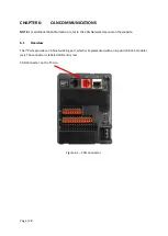
CHAPTER 8: DOWNLOADABLE COMMUNICATION PROTOCOLS
8.1
Overview
Through loadable protocol device drivers, certain models of the
i
³ family can provide the ability to
exchange data with remote devices such as variable-frequency drives, PLCs, and remote I/O devices.
This feature greatly expands the
i
³
’s control capability with negligible effect on the
i
³
’s la
dder scan
time.
Remote devices that communicate serially must do so under certain rules of data transfer known as
a protocol. Many device manufactures have created their own protocol for communications with
their device. For an
i
³ to communicate with a specific device, it must be loaded with the
corresponding serial communications protocol device driver that supports that protocol.
A limited number of protocol device drivers are packaged with the
i
³ Config distribution; however, as
more are developed, they will be made available as add-on packages. A device driver is typically
distributed as a Windows module, which contains the Configuration Menus, Help Files and the
Target Executable Driver Code. When updating device drivers, an install routine loads the device
driver to the
i
³ Config directory structure and makes that driver available to
i
³ Config applications.
Once installed, the protocol device driver can be included as part of a
i
³ Config application by
selecting it from a list of installed protocol device drivers and attaching it to the desired serial port
(Program > Protocol Config menu). Only one protocol device driver can be associated with a serial
port, though some I³ models support multiple protocols on a single Ethernet port.
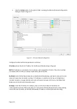
Once the protocol is selected for a specific port, that port must be configured to match the bit
transfer size and rate of the target device(s). This is configured under the
Network Config
menu,
which contains port specific information such as the basic serial port parameters (i.e. baud rate, stop
bits parity, retries, etc.). In addition to the serial port parameters, this menu also contains the
transaction scan update control configuration and any network level protocol specific configuration.
Once the network is configured, each device on the serial communications network must be
configured. For some communications (i.e. RS232), the network can be limited to one device. The
devices are configured under the
Device Config
menu, which contains an arbitrary device name, the
device ID and optionally an
i
³ status register that contains any device fault information.
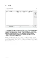
Once each device(s) is configured, a
Scan List
of entries must be created which defines the transfer
of data between a local (
i
³) register(s) and a remote device register(s). These entries are created
under the
Data Mapping
menu, which contains an
i
³ register, a target device ID, a target device
register address, the number of registers to transfer, and update type.
Each entry can be configured for one of two types of initiating a transaction:
Polled and Triggered.
Polled type entries initiate a transaction with the remote device on every transaction scan. Triggered
type entries only initiate a transaction when a corresponding local (
i
³) binary trigger register is
set
.
Once a triggered type transaction completes, the protocol device driver
resets
the local (
i
³) binary
register to indicate completion. See Section 8.5 for more details on Polled and Triggered entries.
These basic types are also subdivided into Read or Write operations. For polled operations, a Read
operation only reads from a remote device. Likewise, a Read/Write operation continuously reads
from the remote device unless the target
i
³ register value changes from one ladder scan to another.
Summary of Contents for i3C Lite
Page 1: ......
Page 8: ...Page 8 ...
Page 65: ...Page 65 Figure 9 3 Screen Calibration ...
Page 78: ...Page 78 Figure 11 2 Relay and Digital Output ...
Page 82: ...Page 82 Figure 11 5 Digital Input ...
Page 86: ...Page 86 11 9 RTD Wiring on J3 Connector ...
Page 110: ...Page 110 Figure 13 8 Alarm Configuration in i Config ...
Page 167: ...Page 167 ...


