


Page | 112
The currealibartioncntly selected entry is indicated by a yellow highlight which can be moved up or
down by touching the arrow buttons or by directly touching an entry. If more entries exist than can fit
on the page, a scroll bar is displayed on the right side that also indicates the current relative position.
File operations are accomplished by pressing the appropriate button at the bottom of the removable
media viewer. The configuration of the removable media object that invokes the removable media
viewer defines what buttons are enabled and available to the user. A button is grayed and does not
respond to touch if configured as disabled.
The (Enter)
button (if enabled) performs certain operations based on the selected file’s type:
..
- change display to parent directory
<DIR>
- change display to child directory
bmp, jpeg
- display bitmap (if compatible format)
pgm
- load application (if compatible model and version)
Alternately, the (enter) button can be configured to simply load the ASCII representation of the file
path (including the file name) to a group of I³ registers. That pathname can then be used by ladder for
opening and manipulating that file.
Once view operations are complete, simply touch the
Esc
button to remove the pop-up removable
media viewer.
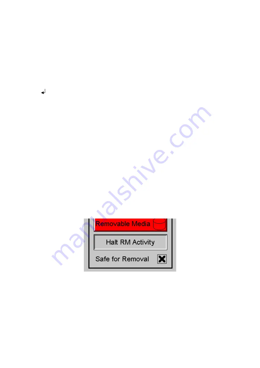
It is best practice to discourage removal of removable media devices by the operator while a write
operation is in process. This can be accomplished by adding a push button to the screen (tied to
%SR174.1), which is used in the logic program to lock out write operations prior to media removal. An
indicator object (tied to %SR174.2) can also be added to the screen, which provides positive
confirmation to the operator that it is safe to remove the media.
Figure 13.11
–
Example application segment for safe removal of removable media
Summary of Contents for i3C Lite
Page 1: ......
Page 8: ...Page 8 ...
Page 65: ...Page 65 Figure 9 3 Screen Calibration ...
Page 78: ...Page 78 Figure 11 2 Relay and Digital Output ...
Page 82: ...Page 82 Figure 11 5 Digital Input ...
Page 86: ...Page 86 11 9 RTD Wiring on J3 Connector ...
Page 110: ...Page 110 Figure 13 8 Alarm Configuration in i Config ...
Page 167: ...Page 167 ...


