background image

DNS-33W  0503  VOL1  (E)

DNS-33W

5.  SETTINGS AND ADJUSTMENT OF CAMERA

5 - 9

• Always press the memory card eject button to remove the

memory card from the slot. When the camera is powered

on, removing the memory card without pressing the

memory card eject button may damage the memory card

data and the memory card itself.

Important:

The camera does not allow a long file name

exceeding 8 characters and 3 filename extension

characters or a file name containing other than half-

size alphabets, such as Chinese characters,

Japanese characters "kana" etc. When saving the

camera data into the memory card which contains

files and folders with those file names, the data

inside the memory card may be destroyed, causing

a problem such as unable to access the data on the

memory card or unable to format the memory card

with the camera.

Notice


If an error occurs during loading/saving, various

error messages are displayed. The error messages

and their definitions are described in the following

table:

There is no memory card in the 

slot.

The inserted memory card cannot 

be used.

An error occurred during saving to 

or loading from the memory card.

The specified data type is different.

There is already a file with the 

same name.

The file could not be created.

There was an error in the data.

The file was not found on the 

memory card.

The data on the memory card was 

not saved by the camera.

CARD INSERT ERROR!

CARD ERROR!

ACCESS ERROR!

! DIFFERENT TYPE DATA

FILE ALREADY EXIST

FILE CREATE ERROR!

FILE DATA ERROR!

FILE NOT FOUND!

NOT SAVE DATA

  FOR CAMERA

Error Message

Definition

Notice


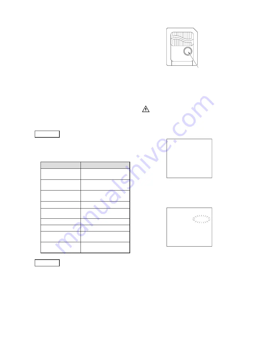
The round sticker attached to the memory card is

used for write protection. Applying the sticker in the

position shown in the next figure prevents formatting

the memory card or overwriting data on the existing

files by mistake.

Always use the sticker supplied with the card for

write protection. Do not touch, wet, etc. to keep the

applied sticker and the metal terminal clean.

Apply the sticker here

Memory Card

5.7.7

Formatting the Memory Card

This section explains how to format memory cards so that

they can be used for DNS-33W.

CAUTION

When a memory card is formatted, all the data

recorded on the card will be lost.

1.

Select "FORMAT/DELETE".

MEMORY   CARD

LOAD FILE             (                 )
LOAD DATA 

   SCENE1-8

LOAD (

CAMERA )

SAVE FILE             (                  )
SAVE DATA 

   SCENE

SAVE (

M.CARD )

FORMAT/DELETE

M.CARD NAME    (                )

2.

The following submenus are displayed. Select

"FORMAT" in detail items. "CANCEL" flashes in the

setting field. Rotate the rotary pulse switch and select

"EXECUTE", then press the SET button.

FORMAT

FORMAT
M.CARD TEST        EXECUTE

DELETE FILE         (                  )
 DATA
DELETE

3.

When the memory card is formatted, "COMPLETE" is

displayed on the screen.

Summary of Contents for Editcam 3 DNS-33W

Page 1: ...rd order FIELDPAK GAIN OUTPUT AWB STBY SAVE L M H CAM BARS A B OFF POWER VF CHARA CH1 CH2 CH1 F R W CH2 F R W CH3 CH4 REAR FRONT F R W AUTO MAN CH3 4 MIX CH4 CH3 4 CH3 CH1 CH2 CH1 2 MIX HYPER GAIN P F...

Page 2: ......

Page 3: ...IELDPAK GAIN OUTPUT AWB STBY SAVE L M H CAM BARS A B OFF POWER VF CHARA CH1 CH2 CH1 F R W CH2 F R W CH3 CH4 REAR FRONT F R W AUTO MAN CH3 4 MIX CH4 CH3 4 CH3 CH1 CH2 CH1 2 MIX HYPER GAIN P FUNC FIL HE...

Page 4: ...ght 2005 Ikegami Tsushinki Co Ltd We reserve the copyright on the software we create No part of this publication may be modified or reproduced in any form or by any means without prior written permiss...

Page 5: ...employs the following hazard alert symbol signal words that indicate the danger levels Notice and Reference for descriptions concerning safety Hazard Alert Symbol Signal Words DANGER WARNING CAUTION...

Page 6: ...icrophone fix the camera on a stable place e g on a table a tripod etc to make the installation easier and to prevent dropping the equipment 7 Avoid use or storage in the following conditions Extremel...

Page 7: ...of the camera Your custom specifications are addressed in CHANGING INFORMATION Changed information is described in this chapter so read this chapter along with other chapters though it may be inconven...

Page 8: ...DNS 33W DNS 33W 0503 VOL1 E...

Page 9: ...4 8 FieldPak Loading and Changing 4 7 4 9 Operations of Recorder Section 4 8 4 10 Operations of Menus of Recorder Section 4 11 4 11 Shooting in Particular Environment 4 13 5 SETTINGS AND ADJUSTMENT O...

Page 10: ...DNS 33W DNS 33W 0503 VOL1 E...

Page 11: ...INSTALLATION AND CONNECTION For details of settings of the camera and recorder section refer to 5 SETTINGS AND ADJUSTMENT OF CAMERA and 6 SETTINGS AND ADJUSTMENT OF RECORDER SECTION DNS 33W 0503 VOL1...

Page 12: ...DNS 33W DNS 33W 0503 VOL1 E...

Page 13: ...ed FP2 has been loaded in the camera the logo Ikegami is displayed and the disk is recognized automatically recognition requires a few minutes For descriptions of each item displayed on the Status scr...

Page 14: ...ssage disappears and when a disk status is displayed FP2 recognition is completed Compression Type Selection Select a data compression type to be used by the camera before shooting 1 Touch the Status...

Page 15: ...When the compression format is changed turn the power ON again Changed settings will be applied after the restart Disk Initialization Initialize format the hard disk of the FP2 Perform this procedure...

Page 16: ...be displayed on the screen When the initialization is completed DISK FORMATTED will be displayed To stop initialization press the CLR button 5 After the initialization is completed press the UP butto...

Page 17: ...O output line is connected to the camera pressing the REC key can record the external input video to an FP2 1 Connect the external VIDEO output line to the GENLOCK IN connector of the camera 2 Select...

Page 18: ...on Control Switch Panel on the Right Side of the Camera Plays recorded image Control Keys on the Top of the Camera EJECT PLAY PRIOR STOP REW NEXT FF Notice Playback on the camera is simplified video W...

Page 19: ...t to DISK Since the recorder section is placed in playback mode for REC REVIEW audio output main is the playback audio which is normal The REC REVIEW playback time can be set at REVIEW LENGTH under PL...

Page 20: ...The TALLY lamp blinks when the RETRO LOOP switch is pressed Image will countinuously be saved to the disk for the specified time length RETRO LOOP Switch How to Set the Retro Loop Length 1 Touch the S...

Page 21: ...ol switch panel CH1 F R W CH2 F R W CH3 CH4 REAR FRONT F R W AUTO MAN SHIFT IN OUT PLAY STOP CH3 4 CH1 2 OUTPUT WIRELESS REC Changes the value by 1 second Changes the value by 10 seconds Changes the v...

Page 22: ...E RECORD button again to confirm the input number Notice When TIMELAPSE RECORD is set at 00 00 00 00 1 frame is shot each time SHIFT REC keys are pressed Audio data is not recorded during the time lap...

Page 23: ...Rewinds 1 second SHIFT Forwards 1 second SHIFT Goes to the prior bin SHIFT Goes to the next bin SHIFT Reduces first digit of input number Increases first digit of input number Reduces second digit of...

Page 24: ...EW SORT DELETE NAME MEDIA TOOLS REBUILD DATABASE RECOVER MEDIA RESET CLIP NUMBER TAPE LABEL DISK SETTINGS DISK WARN SAVE DELAY PARTITIONS UNIT EDIT TOOLS DELETE CLIP RECORD PLAYBACK RECORD RETROLOOP L...

Page 25: ...12 1 Compression type Displays selected compression format for recording Compression formats for the camera is shown below Display Compression Ratio DV25 DVCPRO25 compression DV50 DVCPRO50 compressio...

Page 26: ...deo from the GENLOCK IN connector 8 DISK status Displays operational status of an FP2 9 Clip number Displays recorded first clip number left and last clip number right 10 Current clip number During st...

Page 27: ...rame between OUT point and end point End point last frame of the clip End point of the clip OUT point has been set Frame both IN OUT points have been set 12 Bin name Displays the bin name 13 Audio lev...

Page 28: ...DNS 33W DNS 33W 0503 VOL1 E...

Page 29: ...on can be increased by 30 times for 1 second at maximum This superhigh sensitivity unit also enables special effects such as mirror effect and 30p 240line Usability improvement As a memory card functi...

Page 30: ...on the rear of the camera without cable System operation MA operation with MA adapter MCA 400 supporting 26 pin external VTR connector and camera control unit MA 400 is possible when optional equipmen...

Page 31: ...nector SHUTT SUP V Switch 1 2 3 4 5 6 AWB ABB Switch EARPHONE Terminal REC Button SET Button ROTARY PULSE Switch 7 8 9 10 11 2 NAME AND FUNCTION 1 CABLE Clamp Used to secure the microphone cable and l...

Page 32: ...black shading black set and black balance will be adjusted automatically Setting Value Description 8 EARPHONE Terminal Used to connect the earphone for audio monitor When this terminal is used the so...

Page 33: ...ect the audio signal Switches the audio signal as shown below depending on the audio input LINE MIC 48V ON When line inputting the audio signal to the AUDIO IN CH1 CH2 connectors When connecting a mic...

Page 34: ...his terminal is used the sound from the speaker stopped automatically 10 DC OUT Connector This is a power output connector max 200mA for a wireless receiver and supplies 12V DC power to it 11 CAMERA R...

Page 35: ...OFF POWER VF CHARA 2 3 4 5 6 7 8 9 10 11 12 13 14 15 16 17 18 19 20 21 22 23 24 25 26 27 28 29 30 31 32 33 1 17 18 19 20 21 22 23 24 25 26 27 28 29 30 31 32 33 IEEE1394 Connector CAMERA LEVEL SET Rota...

Page 36: ...12 TIME CODE SELECT Switch Selects the way of the recording time progress F RUN R RUN The recording time goes on regardless of operations of the recorder section This mode is selected when the recordi...

Page 37: ...etting Value Description 26 MONITOR AUDIO PAIR SELECT Switch Used to select the pair of the audio channels CH1 CH2 CH3 CH4 for monitor output 27 MONITOR AUDIO CHANNEL SELECT Switch Used to change the...

Page 38: ...ity asterisk will appear beside ND ECC FILTER indicator of the character display in the VF If a servo controlled ND filter is equipped as an option the control priority of ND filter is changed simulta...

Page 39: ...STOP CH3 4 CH1 2 OUTPUT WIRELESS REC EJECT STOP REW PLAY FF PRIOR NEXT 9 10 11 12 13 14 15 2 3 8 PLAY Key PRIOR Key NEXT Key FF Fast Forward Key REW Rewind Keys STOP Key EJECT Key AUDIO INPUT Switches...

Page 40: ...en performing manual adjustment AUTO only for CH3 and CH4 Setting Value Description 10 AUDIO OUTPUT Switch Used to select output CH1 CH2 or CH3 CH4 from the AUDIO OUT connector on the rear of the came...

Page 41: ...ng these keys during boot up will set all internal non volatile setting to factory defaults Playback SHIFT key PLAY key Plays from current position all clips or events in a continuous loop SHIFT key k...

Page 42: ...OR LOCK Button VF Connector 2 pin Connector for Lighting 11 12 13 14 15 16 17 18 19 20 20 1 RET Button Operation by camera alone When output is CAM side Performs REC REVIEW Plays end of the last recor...

Page 43: ...nected to TC IN connector of external equipment when time code of the external equipment is desired to be locked with the camera 15 GENLOCK IN Connector Input the SYNC signal black burst or composite...

Page 44: ...than the set value 2 6 Viewfinder VF15 32A S This section explains the names and functions of the viewfinder VF15 32A S parts 10 2 2 9 8 7 6 5 4 1 11 3 1 VF Cable EYEPIECE Release Lever Diopter Adjus...

Page 45: ...e the video level is the same as the set value The zebra indicator is turned ON or OFF using the ZEBRA switch on the VF Reference For details of the setting refer to 5 10 5 ZEBRA INDICATOR 2 6 1 Displ...

Page 46: ...select mode for various displays on the VF Switching the Display The character displays can be set by DISPLAY MODE of the camera menu The characters to be displayed on the VF screen differ depending o...

Page 47: ...e recorder section AUDIO level indicator Indicates the input level of audio channels selected by a MONITOR AUDIO SELECT switch located on the right side of the camera Input level for CH1 or CH3 is ind...

Page 48: ...DNS 33W DNS 33W 0503 VOL1 E...

Page 49: ...Connect 3 1 1 Making Sure that Power Switch is Turned OFF Make sure that the power switch is turned OFF when the camera and peripheral equipment are connected For the power switch and turning off proc...

Page 50: ...nch VF 5 inch VF 2 inch VF 1 5 inch VF Zoom Remote Control Tripod Digital Remote Control Cable 1 2 5 10 30m RM 11 Digital Remote Controller MIC Monitor Carrying Case Carrying Case RS 11 Digital Remote...

Page 51: ...TC IN AUDIO OUT MIC IN PRESET AB12 P48 OFF ATT 20dB OFF POWER MAINTE PUSH DNG Camera System with Digital Disk Recorder Digital Remote Control Cable VIDEO OUT ENC Standard SDI Option RM 11 Note Digital...

Page 52: ...t backward slightly 5 After inserting the Front wedge of the camera tighten the Lock lever until the camera is completely fixed At this time rotate the lever until it clicks into position When the cam...

Page 53: ...down the Lens Lock Lever to secure the lens to the camera 4 Connect the Pigtail Cable to the Lens Connector and the Pigtail Cable is automatically locked by aligning and pressing the connector pin to...

Page 54: ...the VF from the Camera 1 Unplug the VF connector while pressing down the connector lock button CAUTION Forcibly unplugging the connector without pressing down the connector lock button will place exc...

Page 55: ...tached attach a microphone holder to the microphone holder attaching mount Various microphone holder options are available depending on the size of the microphone 2 Loosen the screw on the microphone...

Page 56: ...licks 2 Set the AUDIO SELECT switches on the rear of the camera depending on the microphones to be used MON MON Camera Rear Side AUDIO IN CH1 CH2 Connectors Microphone Cable AUDIO SELECT Switches Disc...

Page 57: ...witches of the camera and the AC pack 2 Push the connector release lever and then disconnect the DC cable from the DC OUT connector on the front of the AC pack 3 Push the connector release lever of th...

Page 58: ...G B R G B set in the camera setting mode menu or by the monitor screen During playback the ENC signal of the playback images is output VIDEO OUT connector Outputs the video signal of the camera CAM or...

Page 59: ...through the VIDEO OUT connector 1 Connect VIDEO OUT connector at the left side of the camera and the monitor with a coaxial cable VIDEO GL IN TC OUT TC IN AUDIO OUT PUSH DNG Camera System with Digita...

Page 60: ...DNS 33W DNS 33W 0503 VOL1 E...

Page 61: ...Section 4 2 3 Turning ON Power See Section 4 3 4 Adjusting the Viewfinder See Section 4 4 5 Adjusting the Lens See Section 4 5 6 Output Signal Checks See Section 4 6 8 FieldPak Loading and Changing S...

Page 62: ...FILTER knob 1 100 FIELDPAK switch STBY GAIN SELECT switch L OUTPUT SELECT switch CAM AWB SELECT switch A LCD LIGHT switch ON PANEL switch ON AUDIO INPUT switch Adjust according to the input signal sou...

Page 63: ...to the two types Turn ON the power using the following procedures 1 Turn ON the POWER switches of external system such as AC pack monitor and remote controller 2 Turn ON the POWER switch of the camera...

Page 64: ...IRIS Operation If the iris operation is too slow or on the contrary too fast and causes hunting problems in the AUTO IRIS mode adjust the IRIS GAIN settings of the AUTO IRIS SET of the Maintenance Men...

Page 65: ...lowing procedures 1 Shoot the gray scale chart with the camera 2 Remove the rubber cap with an indication such as Sens IRIS GAIN on it of the grip on the front side of the lens and identify the auto i...

Page 66: ...y stored data 2 Shoot a subject which contains something white Make sure that the following conditions are satisfied The white object must fill at least 10 of the screen There must be no other subject...

Page 67: ...turned off Adjust only the white balance when the color temperature of the lighting has changed When the iris is being set manually it will remain closed even after the ABB has been adjusted Reset th...

Page 68: ...era EXTERNAL External input signal DISK Video signal already recorded on the FP2 4 Select the audio input using the AUDIO INPUT switch on the control switch panel 5 Set the FIELDPAK switch on the righ...

Page 69: ...gles between start and stop of the recording Notice Use the STOP key when stopping the recording of external input video 9 If you want to place the FP2 on standby after recording set the FIELDPAK swit...

Page 70: ...ice To play the same clip again from the beginning press the PLAY key after pressing the IN key When the PLAY key is pressed after the PRIOR key is pressed playback will start from the beginning of th...

Page 71: ...sub menu screen If no clip is selected before deletion the last recorded clip will be deleted YES DELETE CLIP UP NO 7 If you want to place the FP2 on standby after deletion set the FIELDPAK switch on...

Page 72: ...er Input and Character Input Button Selection Change the setting by pressing the button assigned to the item to be selected Screen example PLAYBACK menu PRJ AUDIO SCRUB 0 frames AUD REVIEW LENGTH 5s T...

Page 73: ...the temperature is extremely low where the camera is subject to the direct rays of the sun throughout the day or where an electric field strong enough to put electronic circuits out of order exists i...

Page 74: ...DNS 33W DNS 33W 0503 VOL1 E...

Page 75: ...ivity of the microphone are too high turn ON the MIC ATT switch to lower the level to 20 dB This chapter explains how to set and adjust various camera settings 5 1 Microphone Power Level Down Setting...

Page 76: ...ses an intermittent freeze of a picture Though movement is not smooth this is not a failure When a remote controller is connected the operation of the remote controller has priority over the operation...

Page 77: ...ynamic range than a TV camera Even if the subject has a significant contrast the eye can capture the details in both light and dark parts to a certain extent On the other hand if a TV camera focuses i...

Page 78: ...ning ON OFF the Skin DTL and SKIN DTL Adjusting the SKIN DTL GAIN level Activating the Skin DTL from the remote controller For details on how to operate the various remote controllers refer to the ins...

Page 79: ...8dB SEL 30 36 dB SEL 30 42 dB SEL 30 48 dB Selected Mode HYPER GAIN Value Notice When the HYPER GAIN function is activated the noise component increases as well as the gain becomes high The HYPER GAIN...

Page 80: ...n Metal Terminal Front Side of Memory Card Back Side of Memory Card CAUTION Ensure that the memory card is facing the right way metal terminal facing down when inserting it to the memory card slot 2 P...

Page 81: ...played after COMPLETED and the camera will be restarted 6 Press the memory card eject button and remove the memory card The procedures above load the camera setting file saved on the memory card to th...

Page 82: ...Naming the Memory Card The memory card can be named MEMORY CARD LOAD FILE LOAD DATA SCENE1 8 LOAD CAMERA SAVE FILE SAVE DATA SCENE SAVE M CARD FORMAT DELETE M CARD NAME 1 Select M CARD NAME The flash...

Page 83: ...le could not be created There was an error in the data The file was not found on the memory card The data on the memory card was not saved by the camera CARD INSERT ERROR CARD ERROR ACCESS ERROR DIFFE...

Page 84: ...unction is allocated to the P FUNC switch Turns ON OFF the mode to adjust the iris by approximately 1 2 STOP when AUTO IRIS is set Turns ON OFF the mode to adjust the iris by 1 STOP when AUTO IRIS is...

Page 85: ...e square window appears in the middle of the VF The white square for the AHD disappears if no operation is carried out in 10 seconds and the AHD function is also cancelled A White Square Window 2 Adju...

Page 86: ...rst or second message is displayed will end the message display and cancels the initialization 5 10 Settings in the Menu There are two menu modes available for DNS 33W Normal Menu and Maintenance Menu...

Page 87: ...section explains how to operate the Maintenance Menu There are 3 screens for the Maintenance Menu MENU 1 3 MENU 2 3 and MENU 3 3 Their operation procedures are basically the same as the Normal Menu V...

Page 88: ...lects the display mode for various characters displayed on the VF 1 to 100 65 Sets the video level of markers and characters Switches the aspect ratio of the safety marker display Turns ON OFF the cen...

Page 89: ...CANCEL READY OTHERS RET SOURCE VTR VIDEO GL VIDEO VTR VIDEO Selects whether to turn the RET video signal into VTR video or GL VIDEO Selects whether to make the iris cap interact when in BAR ON settin...

Page 90: ...or TITLE displays the title area from SAFETY AREA SAFETY MARKER turns ON OFF the safety marker display and SAFETY ASPECT selects the aspect ratio of the safety markers from 4 3 13 9 14 9 15 9 and 16 9...

Page 91: ...lue 2 Confirm the value by pressing the SET button DISPLAY SELECT Character display setting DISPLAY SELECT turns each character display ON OFF 1 Select DISPLAY SELECT The following submenu screen is d...

Page 92: ...ONITOR OUT2 Submenus to select mode for various displays on the monitor line MONITOR OUT2 sets up the item contents to display on the monitor for example the brightness of the marker display etc MONIT...

Page 93: ...ulse switch to select ON or OFF If ON is selected for a function the indicator turns on when the function is activated 4 Confirm the selection by pressing the SET button 5 On the CURRENT column asteri...

Page 94: ...refer to 5 6 2 Activating the HYPER GAIN 5 10 9 BATT DISK WARNING BATT DISK WARNING BATT DISK WARNING sets up whether to light the FRONT TALLY lamp or BACK TALLY lamp when the battery voltage the rem...

Page 95: ...return this level to the factory setting activate the auto black balance For details on auto black balance operations refer to 4 7 Auto White Balance Auto Black Balance and Auto Black Shading DTL GAI...

Page 96: ...e AWB memory and set it to Ach Does not cancel the OFF setting in the AWB memory Setting Value Description If the previous setting is AWB OFF when a remote controller without the AWB memory switch fun...

Page 97: ...play Turns ON OFF the frame marker display Switches the aspect ratio of the frame marker display Turns ON OFF the side mask function The side mask function changes the video level of the picture outsi...

Page 98: ...y ON OFF BATT DISK WARNING Refer to the 5 10 9 BATT DISK WARNING of the Normal Menu for details on the operation procedures and the function description SCENE FILE Refer to the 5 10 10 SCENE FILE of t...

Page 99: ...urns ON OFF the shock less AWB mode and sets up the operation time Turns ON OFF AWB memory for each ECC filter Turns ON OFF the function to use the set value for AWB conclusive value Creates a normal...

Page 100: ...MA FLARE MANUAL KNEE AUTO KNEE WHT CLIP DTL 1 2 DTL 2 2 SOFT DTL R COLOR CORR G COLOR CORR B COLOR CORR C COLOR CORR M COLOR CORR Y COLOR CORR MATRIX COL SAT G L PHASE R WHT SHADING G WHT SHADING B WH...

Page 101: ...s the file from the memory card Save the data on the memory card 8 characters ALL DATA SNAP SHOT SCENE REFERENCE LENS SAVE FILE SAVE DATA ALL DATA SAVE M CARD FORMAT DELETE FORMAT M CARD TEST DELETE F...

Page 102: ...oller is disabled When the SEMI REMOTE MODE is OFF the control priority of these switches is switched to the remote controller and turning ON OFF a function from the camera is disabled GAIN SELECT swi...

Page 103: ...his operation will not be executed Notice This function cannot be activated if the S2 switch red slide switch of MPU module is not set to ON at the top To prevent miss operation the S2 switch is set t...

Page 104: ...t the VR on the lens side so that each of F2 8 and F16 match 7 When the adjustment is complete set LENS ADJUST to OFF and press the SET button Exiting from this menu mode will automatically change the...

Page 105: ...to create a lens file refer to the next section Notice When IRIS LIMIT is activated the F value display in the VF flashes Just turning the rotary pulse switch to F2 8 or F16 will output the control vo...

Page 106: ...front side of the camera to AWB Auto white shading is executed and a lens off file is created automatically Notice Check the following items when making a lens off file or a lens file of an optional l...

Page 107: ...in use Then create files under the same condition all at one time If the condition are changed the setting can t be accurate Lens file memorizes the difference in level between lenses If lighting and...

Page 108: ...stop controlling methods of VTR for broadcasting When the controlling method is unknown try EDGE TRIG first 26P VIDEO SEL Setting 26P VIDEO SEL will select the component signal type output from the 26...

Page 109: ...camera and their levels CAL PULSE Turning ON CAL PULSE will output a sawtooth calibration pulse It is set to OFF normally EFFECT MODE Selects the special function to operate when an optional D PROC S...

Page 110: ...n of MON OUT is the same function as the OUTPUT SIGNAL of MONITOR OUT submenu on the Normal Menu and the Maintenance Menu Therefore no matter from which menu the signal type was set the later set sign...

Page 111: ...ads lens file No 8 LENS1 8 LENS1 LENS2 LENS3 LENS4 LENS5 LENS6 LENS7 LENS8 Setting Value Description When loading files set to REFERENCE in SAVE DATA the following item can be set Loads the reference...

Page 112: ...button in this state SAVING is displayed and the saving starts 3 When COMPLETED is displayed the saving is completed 4 To cancel the saving operation rotate the rotary pulse switch to execute CANCEL...

Page 113: ...to be deleted using the rotary pulse switch The data format of the selected file will be displayed next to DATA 3 Press the SET button to confirm DELETE Deletes the file selected in DELETE FILE from...

Page 114: ...ng the RET and VTR buttons on the lens RET VTR RET button for RET1 VTR for RET2 RET VTR Press VTR button while pressing and holding RET button to switch the RET channel RET CH SEL SW RET VTR RET VTR R...

Page 115: ...CUSTOMIZE VF DISPLAY MONITOR OUT ZEBRA INDICATOR INDICATOR BARS TITLE MODE LOW MID HIGH GAIN MODE BATT DISK WARNING SCENE FILE LEVEL ADJUST CPU SYSTEM CONTROL AWB ABB MODE AUTO IRIS SET G L PHASE ADJ...

Page 116: ...DNS 33W DNS 33W 0503 VOL1 E...

Page 117: ...ton is pressed while OFF is displayed 7 UP Returns to the BASE menu Notice The test tone cannot be recorded on an FP2 The recording function of the external input video is optional This chapter explai...

Page 118: ...When the Compression Format is DV When the Compression Format is JFIF When the Compression Format is MPEG Notice Clips with different compression format cannot co exist in an FP2 On the other hand cl...

Page 119: ...he horizontal direction for the playback video signal Set the value between 80 and 80 e UP Returns to the VIDEO menu 6 2 3 AUDIO Menu HEADROOM 14dB TONE FREQ 800hz TC UP METERS LINEAR 1 3 3 4 5 2 TC T...

Page 120: ...FT or SHIFT or or Changes the value by hour Changes the value by minute Changes the value by second Changes the value by frame Operated Key Description or FREE RUN Sets a time code data 00 00 00 to 23...

Page 121: ...AT DISK PAK 1 CLR Pressing the OK button while pressing the SHIFT key starts initialization by the compression type selected in the PROJECT menu When the initialization is completed the screen switche...

Page 122: ...DELETE Following operation deletes all the clips in the selected bin or the bin itself When deleting all the clips in the bin at once Use the key and the key to select the bin that contains the clips...

Page 123: ...P Returns to the DISK OPERATIONS menu 6 3 4 DISK SETTINGS Menu UNIT 0 VID VID DISK WARN 02 00 mmss PRJ SAVE DELAY 00 15 mmss TC UP PARTITIONS FAT32 4 5 1 2 3 1 DISK WARN Sets the value to warn the rem...

Page 124: ...Pressing the YES button deletes the selected clip Pressing the NO button does not delete the selected clip and returns to the EDIT TOOLS menu 2 UP Returns to the DISK OPERATIONS menu 6 4 RECORD PLAYBA...

Page 125: ...s as TIMELAPSE OUT OF will be played at 15 frames as TIMELAPSE RECORD Record interval 6 25 10 frames 15 Timelapse setting example Set time lapse record to 15 frames Set out of to 6 real time seconds F...

Page 126: ...t of the mark IN point 128 to 127 3 MARKOUT OFFSET Sets the offset of the mark OUT point 128 to 127 4 Clip Position Set Button Sets the offset from the position set by CLIP POSITION 5 UP Returns to th...

Page 127: ...ternal clock in 24 hour format C TIME 10 44 05 hhmmss DAY Wed VER DATE 04 09 22 yymmdd LIC UP SET TIME 1 5 2 3 4 1 TIME Sets the time of the internal clock or or Changes the value by hour Changes the...

Page 128: ...ing information of the recorder section from an FP2 Press this button after the FP2 is loaded d RESTORE FROM SM Restores setting information of the recorder section from a memory card Press this butto...

Page 129: ...by 1V Changes the value by 0 1V Operated Key Description or c Power Levels CUTOFF Sets a cutoff voltage from the DC input 8 0 to 15 0V When the voltage reaches to the specified value the recording op...

Page 130: ...tion where the button responds when actually touched are out of line in the vertical direction 3 BG COLOR Selects the background color of the Status screen Select one from 9 colors below BLACK RED YEL...

Page 131: ...er section Press the REC key on the control switch panel to start recording Turn ON the LCD Light switch When restarting the camera turn on the power 10 seconds or more after powering off Turn ON the...

Page 132: ...ecommended that a color monitor be used to check the images during the inspection Checking the Positions of the Switches Before turning the POWER switch ON check that the following switches knobs etc...

Page 133: ...before shooting to check if the VF works normally 1 Adjust the VF position For details refer to 3 4 Mounting the Viewfinder Adjusting the Angle and Position 2 Check that color bars appear in the viewf...

Page 134: ...rol and Motorized Zoom Functions Inspect following items before shooting to check if the automatic aperture control and motorized zoom functions of the lens work normally 1 Set the ZOOM OPERATION SELE...

Page 135: ...4 Option Operations on all PCs with IEEE1394 terminal and software are not guaranteed Regardless of compression type selected in the recorder section a DV stream signal is always output from this term...

Page 136: ...DNS 33W DNS 33W 0503 VOL1 E...

Page 137: ...36 42 48 dB Electronic shutter Preset NTSC 1 60 OFF 1 100 1 120 1 250 1 1000 1 2000 PAL 1 50 OFF 1 100 1 120 1 250 1 1000 1 2000 Variable NTSC 2H 1 7867sec to 260H 1 60 5sec PAL 2H 1 7812sec to 310H...

Page 138: ...ected as option output to the camera s IEEE1394 connector Output to the VF connector Output to the camera s XLR connector Microphone power supply 48V Phantom OFF AB12V selectable MIC connector 48V Pha...

Page 139: ...TALLY IND GAIN 3 0 3 6 9 12 18 24 30 36 42 48 dB GAMMA OFF 0 35 0 40 0 45 HYPER GAIN 30 36 42 48 dB IRIS ADJUST KNEE KNEE APERTURE LENS EXTENDER IND MATRIX MON SELE ENC Y R G B R G B PERSONAL FUNCTIO...

Page 140: ...uipment is connected VF RET VTR POWER SAVE VF CHARA Only applicable for RM 11 VTR START STOP WHITE SHADING Capable of 2 zone zebra indicator ZEBRA IND WHITE CLIP SUPER KNEE OFF LOW MID HIGH SKIN DTL S...

Page 141: ...COLOR SATURATION Sets the amount of V DTL edge DTL BALANCE DTL BOOST FREQUENCY DTL GAIN DTL NOISE SUP DTL THRESHOLD FLARE GAIN IRIS KNEE POINT AUTO MANUAL KNEE SLOPE AUTO MANUAL MATRIX SOFT DTL VARIAB...

Page 142: ...B OFF POWER VF CHARA CH1 CH2 CH1 F R W CH2 F R W CH3 CH4 REAR FRONT F R W AUTO MAN CH3 4 MIX CH4 CH3 4 CH3 CH1 CH2 CH1 2 MIX HYPER GAIN P FUNC FIL HEAD 4 1 6 36 2 22 5 11 0 ND D 8 00 0K C 6 30 0K B 4...

Page 143: ...MIC IN PRESET AB12 P48 OFF ATT OFF POWER MAINTE PUSH DNG Camera System with Digital Disk Recorder 20dB VIDEO GL IN TC OUT TC IN VIDEO GL IN TC OUT TC IN REAR 1 REAR 2 LINE MIC 48V ATT 20dB OFF LINE M...

Page 144: ...DNS 33W DNS 33W 0503 VOL1 E 8 8 8 SPECIFICATIONS 8 3 3 Front Side View LOW HIGH OFF ON TALLY ZEBRA BRIGHT CONTRAST PEAKING LENS ON OFF AWB ABB SHUTT SUP V MENU VTR AUDIO OUT 94 3 7 119 3 127 Unit mm...

Page 145: ...DNS 33W 0503 VOL1 E DNS 33W 8 SPECIFICATIONS 8 9 8 3 4 Rear Side View DC OUT REMOTE DC IN MON REAR 1 REAR 2 LINE MIC 48V ATT 20dB OFF LINE MIC 48V PHONE 127 DC OUT DC IN PHONE Unit mm...

Page 146: ...2 8 1 4 9 OUT AUTO 5V B4 IRIS SERVO ON B3 5 6 RETURN VIDEO ON OFF signal RETURN ON GND RETURN OFF OPEN RET START STOP control signal OUT IN 12V LENS IRIS FOLLOW IRIS REMOTE LOCAL AUTO signal REMOTE 4...

Page 147: ...0 OUT LENS COMMON REC TRIGGER DIASCOPE ON For common power output of lens nominal 6V Intermediate potential between 12V lens and GND 12V LENS LENS COMMON REC START STOP control signal IN 4 3 STOP STAR...

Page 148: ...valent 3 pin male plug MIC SHIELD MIC input shield 1 MIC HOT IN MIC HOT line 600 balanced input When 12V AB power is supplied DC 12V When 48V phantom power is supplied DC 48V 2 3 MIC COLD MIC COLD lin...

Page 149: ...oller to camera IN HEC IN Digital data output to remote controller from camera HEAD OUT 9 10 ENABLE signal input from remote controller External output of R TALLY signal REM SENSE 6 NC 5 3 R TALLY OUT...

Page 150: ...ignal for serial parallel data conversion SP WR OUT RET 10 Serial data signal for serial parallel data conversion VF SP DATA 11 ZEBRA signal ON OFF switching ZEBRA ON IN 12 NC 13 14 15 16 RET RET RET...

Page 151: ...ale plug MIC input LINE input LINE SHIELD LINE HOT LINE COLD Shield for LINE input LINE HOT line LINE COLD line IN IN Insertion Side Receptacle Pin No Name Function I O External Interface Pin No Name...

Page 152: ...witches to EXT when a plug is inserted GND IN GND This connector has a built in switch NC Normally close opens when the connector is connected NO Normally open closes when the connector is connected S...

Page 153: ...DNS 33W 0503 VOL1 E DNS 33W Revision contents in case of design revision and at request of customers are explained here Read by comparing this information with the main part of the operation manual C...

Page 154: ...DNS 33W DNS 33W 0503 VOL1 E...

Page 155: ...period is already over Ikegami will repair the product for payment if the repair is possible Note There are cases of charged repair even in the guarantee period Please read the guarantee thoroughly Wh...

Page 156: ...DNS 33W DNS 33W 0503 VOL1 E...

Page 157: ...Ikegami Tsushinki Co Ltd Mar 2005 Ikegami Tsushinki Co Ltd All rights reserved Reproduction or duplication without permission of Ikegami Tsushinki Co Ltd of editorial or pictorial content in whole or...

Page 158: ......

Page 159: ......

Page 160: ...SU J Fax 03 5700 1137 Ikegami Electronics U S A Inc 37 Brook Avenue Maywood New Jersey 07607 U S A Phone 201 368 9171 Telex 219034 ITCNJ UR Fax 201 569 1626 Ikegami Electronics Europe GmbH Ikegami Str...

Reviews: