NAV6
plus
NAVTEX System User Guide
60
•
When inserting cores into the terminal strip take care not to screw
down on the plastic insulation
Note. the ‘black’ of the ‘green pair’ in not used, it is folded and
sleeved back out of the way.
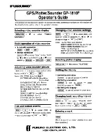
Connecting the Sensor
Connecting the Sensor
Connecting the Sensor
Connecting the Sensor
•
Connect the YELLOW and BLACK twisted pair from the sensor to
the YELLOW and BLACK twisted pair of the display
•
Connect the WHITE and BLACK twisted pair from the sensor
display to the WHITE and BLACK twisted pair of the display
•
Connect the silver, (screen) wires together. Do not connect them to
a power supply 0V, refer to note below regarding system grounding
Power supply
Power supply
Power supply
Power supply
Connect the RED wire to boat’s positive (12V) supply and the BLACK
wire to negative (0V) supply.
NAV6 PRINTER
NAV
Printer
6
SENSOR
GPS
BATTERY
Na
vt
ex
ICS
NAV-6 ANTENNA
* Not connected
BLACK*
SCREEN DRAIN
BLACK/YELLOW
YELLOW/BLACK
A
BLUE
RX
TX
B
BLACK
BROWN
BLACK
YELLOW
BLACK
SCREEN DRAIN
+12V
GND
RED
BLACK
GREEN
BLACK/WHITE
WHITE/BLACK
WHITE
BLACK
DISPLAY
NAV-6
Summary of Contents for Nav6plus
Page 11: ...NAV6plus NAVTEX System User Guide 11...
Page 42: ...NAV6plus NAVTEX System User Guide 42 Contact your supplier for further information...
Page 46: ...NAV6plus NAVTEX System User Guide 46...
Page 52: ...NAV6plus NAVTEX System User Guide 52 page 62 of this user guide...