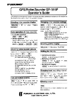
background image

www.furuno.com

All brand and product names are trademarks, registered trademarks or service marks of their respective holders.

Installation Manual

IMPORTANT NOTICES AND SAFETY INSTRUCTIONS ..........i
SYSTEM CONFIGURATION ....................................................iii
EQUIPMENT LIST ....................................................................iv

1. INSTALLATION....................................................................1

1.1 Disply Unit Installation..................................................................1
1.2 Radar Sensor (DRS4W) Installation............................................4
1.3 Transducer Installation................................................................5
1.4 Speed/Temperature Sensor (Option) Installation......................14

2. WIRING...............................................................................15

2.1 Power/NMEA0183 Port.............................................................15
2.2 XDR Port.....................................................................................16
2.3 NMEA2000 (CAN bus) Connections..........................................17

3. SETTINGS AND ADJUSTMENTS .....................................18

3.1 Starting the Setup Procedure.....................................................18
3.2 How to Use the Menu................................................................19
3.3 Initial Setup Menu.......................................................................20
3.4 How to Set Up the Fish Finder..................................................24
3.5 How to Set Up the Radar...........................................................25

4. INPUT/OUTPUT DATA........................................................27

4.1 How to access the [Interface] menu...........................................27
4.2 How to set up for NMEA0183 configurations .............................27
4.3 How to select a data source.......................................................27
4.4 How to select which NMEA2000 data to output.........................28
4.5 How to select which NMEA0183 sentence to output .................28
4.6 How to calibrate (offset) the sensors .........................................29
4.7 How to reset the [Interface] menu..............................................30
4.8 NMEA0183/NMEA2000 Monitor.................................................30

5. MAINTENANCE AND TROUBLESHOOTING ....................31

5.1 General Maintenance.................................................................31
5.2 Life of Parts................................................................................32
5.3 Troubleshooting .........................................................................32
5.4 How to Restore the Default Settings..........................................34
5.5 How to View the System Information .........................................34

APPENDIX 1 MENU TREE ................................................. AP-1
APPENDIX 2 RADIO REGULATORY  INFORMATION ......AP-9
SPECIFICATIONS ................................................................SP-1
OUTLINE DRAWINGS ...........................................................D-1
INTERCONNECTION DIAGRAM ...........................................S-1

GPS/WAAS COLOR CHART PLOTTER with FISH FINDER

Model

 GP-1871F/GP-1971F

Summary of Contents for GP-1871F

Page 1: ...t Up the Fish Finder 24 3 5 How to Set Up the Radar 25 4 INPUT OUTPUT DATA 27 4 1 How to access the Interface menu 27 4 2 How to set up for NMEA0183 configurations 27 4 3 How to select a data source 27 4 4 How to select which NMEA2000 data to output 28 4 5 How to select which NMEA0183 sentence to output 28 4 6 How to calibrate offset the sensors 29 4 7 How to reset the Interface menu 30 4 8 NMEA01...

Page 2: ...e number of symbols can in crease when the other countries make their own recycle symbols in the future Cd Ni Cd Pb IMPORTANT NOTICES AND SAFETY INSTRUCTIONS ii Safety Instructions Read these safety instructions before you install or operate the equipment Use only the specified power and signal cable Fire or damage to the equipment can result if a different cable is used WARNING CAUTION Warning Ca...

Page 3: ...lation Materials 1 Accessories 1 Spare Parts 1 Name Type Code No Remarks Matching Box MB 1100 000 027 226 Junction Box FI 5002 000 010 765 Temperature Sensor T 04MSB 000 026 893 Thru hull type T 04MTB 000 026 894 Transom mount Speed Temperature Sensor ST 02MSB 000 137 986 01 Thru hull type metal ST 02PSB 000 137 987 01 Thru hull type plastic Inner Hull Mounting Kit 22S0191 3 001 321 930 Cable Asse...

Page 4: ...th the radar sensor Signals are strongest to the fore aft direction of the unit weakest to either side of the unit The unit should be located within the following distances from the radar sensor to ensure a stable connection Vessels with no obstructions approximately 5 m or less Vessels with obstructions approximately 2 m or less Avoid locations where the obstruction s are composed of metal carbon...

Page 5: ...lied NMEA2000 connector cap to the NMEA2000 connector at the rear of the Display Unit If your configuration has NMEA2000 connections discard the connector cap Slots face forwards Slots face forwards 4 8 22 SUS304 four locations 1 INSTALLATION 3 1 1 2 Flushmount console installation Before mounting the Display Unit in a desktop or console remove the unit from the attached bracket 1 Unfasten the two...

Page 6: ...sing The installation should be planned in advance keeping the length of the transducer cable and the following factors in mind Air bubbles and turbulence caused by movement of the boat seriously degrade the sounding capability of the transducer The transducer should therefore be located in a position where water flow is the smoothest Noise from the propellers also ad versely affects performance a...

Page 7: ...d soap This will lessen the time necessary for the transducer to have good contact with the water Otherwise the time required for complete saturation will be lengthened and performance will be reduced DO NOT paint the transducer Performance will be affected Hole for stuffing tube Saw along slope of hull Upper Half Lower Half BOW Deep V Hull Flat Washer Rubber Washer Fairing Block Hull Flat Hull Hu...

Page 8: ...tion procedure below Mount the transducer at a location 1 2 to 1 3 of the length of your boat from the stern The mounting location is between 15 to 50 cm from the centerline of the hull Do not place the transducer over hull struts or ribs which run under the hull Avoid a location where the rising angle of the hull exceeds 15 to minimize the effect of the boat s rolling 1 INSTALLATION 9 9 Tap the i...

Page 9: ... bracket 1 Cut out the installation template enclosed with transducer along the dotted line 2 At the selected location position the template so the arrow at the bottom is aligned with the bottom edge of the transom Being sure the template is parallel to the waterline tape it in place Warning Always wear safety gog gles and a dust mask 3 Using a 4 mm 23 or 9 64 bit drill three holes 22 mm 7 8 deep ...

Page 10: ...secure the cable against the transom using the cable clamps Position a cable clamp 50 mm 2 above the bracket and mark the mounting hole with a pencil 4 Position the second cable clamp halfway between the first clamp and the cable hole Mark this mounting hole 5 If a hole has been drilled in the transom open the appropriate slot in the transom cable cover Position the cover over the cable where it e...

Page 11: ... casing through the hole 6 Face the notch on the sensor toward boat s bow and tighten the flange 7 Set the sensor section to the sensor casing and tighten the locknut 8 Launch your boat and check for water leakage around the sensor 1 4 2 Temperature sensors T 04MSB and T 04MTB For installation instructions for T 04MSB and T 04MTB sensors see the installation instructions included with the sensor L...

Page 12: ...ections error in individual fish detection Wrong speed data No TD ID recognition NMEA0183 Pin Assignment 1 2 3 4 5 6 7 8 1 Black 20AWG 2 Red 20AWG 3 White 22AWG 4 Green 22AWG 5 Gray 22AWG 6 Yellow 22AWG 7 Blue 22AWG 8 Drain wire VIN VIN TD A NMEA0183 RD B NMEA0183 GND RD A NMEA0183 TD B NMEA0183 SHIELD Pin Wire Color Signal Name 2 WIRING 17 2 3 NMEA2000 CAN bus Connections What is CAN bus CAN bus ...

Page 13: ...ke sure both these menu items are set to OFF 3 SETTINGS AND ADJUSTMENTS 19 3 2 How to Use the Menu The Settings menu contains customizing options for this equipment To access the Settings menu follow the procedure below 1 Tap the Home icon to show the Home screen 2 Tap Settings The Settings menu appears 3 Tap the menu you want to access Drag the menu to show menu items which do not appear on scree...

Page 14: ...tion fixing ship s ve locity speed is directly mea sured from the GPS satellite The raw velocity data may change randomly depending on receiving conditions and other factors You can reduce this random variation by increasing the filter setting If the setting is too high however the response to speed and course change slows Off Low Medium High Map Datum Select the datum to use For nor mal use selec...

Page 15: ...t empty 0 ohm to 500 ohm Capacity Set the maximum capacity of the tank 0 to 9999 Self Test Start a diagnostic test of the de vices connected via the IF NMEA Refresh Refresh the list of connected de vices Rudder Setup tab PORT STBD Reversing Select whether or not to set port and starboard in reverse ON OFF About tab System Information Software Version Software version for the GP 1x71F Boot Version ...

Page 16: ...h indication Select Small or Large to show the appropriately size indication or Off to hide the in dication 3 SETTINGS AND ADJUSTMENTS 25 3 5 How to Set Up the Radar 3 5 1 How to connect to the DRS4W Radar Sensor If you have a DRS4W radar antenna you can connect to the antenna via wireless LAN Before adjusting settings for the radar make sure the antenna is turned on Note For how to turn the DRS4W...

Page 17: ...arent position of target Apparent position of target Antenna mounted error to starboard HDG SW delayed Picture appears deviated counterclockwise Front of antenna Front of antenna a b 27 4 INPUT OUTPUT DATA The GP 1x71F can connect to temperature sensors speed sensors and other NMEA0183 or NMEA2000 compatible sensors To connect and communicate with most sensors sensor settings in the Interface menu...

Page 18: ...ate 129026 COG SOG Rapid Update 129029 GNSS Position Data 129033 Time Date 129283 Cross Track Error 129284 Navigation Data 129285 Navigation Route WP Information 130310 Environmental Parameters 130312 Temperature 130316 Temperature Extended Range 130830 Target Information 130831 Target Bottom Classification Data 130832 Target Fish Length 4 INPUT OUTPUT DATA 29 4 Tap the u at the top right of the s...

Page 19: ...d condition and prevents fu ture problems Check the items shown in the table below on a regular basis to help keep your equipment in good condition for years to come Check item Check point Remedy Cables Cable connection corrosion Connect reconnect the cables that have loosened or disconnected Replace any damaged cables Display unit Dust on the display unit Remove dust with a dry clean cloth Do not...

Page 20: ...ce is correct Marks and characters appear but echoes do not appear Check if the radar source is correct Picture is not updated or the picture freezes Check that there are no obstructions between the antenna and the display unit If the picture has frozen turn the power off and on again You tuned the receiver but the sensitivity is weak The life span of the magnetron is over Have a technician check ...

Page 21: ...ec 10 sec 30 sec 1 min 5 min 10 min 30 min 1 h 1 Settings menu General Function Gestures Key Beep Date and Time Color Schemes Wireless LAN Quick Guide Ship Track COG Vector Track Recording Track Color Type Single Color Multi color Multi color Reference Depth Temperature Speed Bottom Discrimination Thickness 1 px 2 px 3 px Delete Options Color Single Track Red Green Blue Yellow Cyan Magenta Brown G...

Page 22: ... High Res Fishing Bathymetry ON OFF VAD Objects APPENDIX 1 MENU TREE AP 3 1 2 2 1 Chart Aspect Mode Mode 2D 3D Layer Vector Shaded Relief Satellite Raster Chart Layer Overlay No Raster Layer On Land On Sea On All 3D Exaggeration Level 1 to Level 5 Layer Transparency 0 to 100 default 50 Baud Rate 4800 38400 Position SOG COG Internal GPS NMEA0183 NMEA2000 Auto Heading NMEA0183 NMEA2000 Auto Wind NME...

Page 23: ...dow Restore Defaults Restore Default Settings Select Yes No from pop up window For CHIRP transducers the Offsets menu appears as follows Offsets Gain 50 to 50 default 0 Bottom Level 100 to 100 default 0 APPENDIX 1 MENU TREE AP 5 1 1 Notifications General Navigation Tanks Wind AIS Fish and Bottom Buzzer ON OFF Buzzer Sound Grounding ON OFF Grounding Depth ft 0 to 65 6 default 32 8 Depth Range ft 0 ...

Page 24: ...02 F 122 to 410 F Engine Oil Temperature 86 to 302 F 122 to 410 F Transmission Temperature 86 to 302 F 122 to 410 F Language English US English UK others Vessel Autopilot Data Acquisition SC 30 Setup Instruments Range Setup SBAS Mode ON OFF Restart GPS Dynamic Model At Sea Automotive Navigation Speed Low High Internal GPS Setup Position Filter Off Low Medium High Speed Filter Off Low Medium High M...

Page 25: ... should be installed and operated keeping the radiator at least 20cm or more away from person s body This device must not be co located or operating in conjunction with any other antenna or transmitter Canada Industry Canada IC This device complies with Industry Canada licence exempt RSS standard s Operation is subject to the following two conditions 1 This device may not cause interference and 2 ...

Page 26: ...W 600 W or 1 kW 4 3 Transmit interval 2000 times min 4 4 Pulselength 0 04 to 3 0 ms 4 5 Sensitivity 10 dBμV 4 6 Range Display range 5 to 1200 m Shift 0 to 500 m 4 7 Picture advance speed Stop 1 16 1 8 1 4 1 2 1 1 2 1 4 1 4 8 Other functions ACCU FISHTM RezBoostTM Chirp Bottom discrimination 5 INTERFACE 5 1 Number of port NMEA0183 1 port NMEA2000 1 port micro connector LEN 1 FURUNO GP 1871F 1971F S...

Page 27: ...D 1 11 Sep 2017 H MAKI 11 Sep 2017 H MAKI ...

Page 28: ...D 2 11 Sep 2017 H MAKI 11 Sep 2017 H MAKI ...

Page 29: ...D 3 11 Sep 2017 H MAKI 11 Sep 2017 H MAKI ...

Page 30: ...D 4 11 Sep 2017 H MAKI 11 Sep 2017 H MAKI ...

Page 31: ...ࣥࢧ ཷἼჾ 67 06 67 3 7 7 7 3 7 6 66 6 7 ᗈᖏᇦ ཷἼჾ 53 75 16 8 5 0 66 0 0 70 0 67 06 67 36 7 06 36 06 3 Ỉ ࢭࣥࢧ 63 7 03 6 1625 3 ࡲࡓࡣ 25 Ỉ ࢭࣥࢧ 7 03 6 1625 0 63 0 63 ཷἼჾ 75 16 8 5 6 7 7 N 0 0 7 1 2 5 5 㺖㺹 㺏㺔 㺖㺹 㺏㺔 P P P 5 P 5B6 5B1 5B3 6 7 N 0 㺖㺹 8 㺏㺓 51 㺮㺢㺼㺶 5 㺏㺔 P 5 P ȭ P P 9 ᢠ 7 50 1 725 58 0 㺰㺛 0 58 00 㺓㺛 0 66 0 ࢣ ࣈࣝ ရ 58 10 300 P ࡲࡓࡣ 25 ἲ 1 9 48 30 17 5 7 7 5 7 211 725 58 00 0 0 7ࢥࢿࢡࢱ 0 63 P 10 7 219 57...

Page 32: ... etc g Sea trial test and evaluation or other demonstrations h Products repaired or altered by anyone other than the FURUNO national distributor or an authorized dealer i Products on which the serial number is altered defaced or removed j Problems resulting from an accident negligence misuse improper installation vandalism or water penetration k Damage resulting from a force majeure or other natur...

Page 33: ...7KH SDSHU XVHG LQ WKLV PDQXDO LV HOHPHQWDO FKORULQH IUHH 85812 XWKRUL HG LVWULEXWRU HDOHU VKLKDUD FKR 1LVKLQRPL D 3 1 0 5 3ULQWHG LQ DSDQ OO ULJKWV UHVHUYHG 81 3XE 1R 0 5 3 ...

Reviews: