background image

CS-F620TR Programming Software Manual 

(rev 1.0) - 

LTR Programming Screen

34

Group

Field

Description

Default

Suggested
Settings

Scrambler

ON/OFF

Select “OFF,” “ON” or “Inhibit”. Setting this
to “OFF” sets the scrambler off as an initial
setting. Setting this to “ON” turns the
scrambler on as an initial setting. The

Scrambler

 key can then be used to toggle this

function on and off. Setting this field to “Inh”
(Inhibit) will prevent the scrambler from being
used while this system is selected. See the
Scrambler Type field in the 

Common

programming screen (page 60) for more
information on setting up the scrambler.

OFF
(Blank)

Set as
needed.

Scrambler

Code

Set from 1 to 255. With the UT-109 (“Non-
Rolling” type) only the value 1 through 32 will
work. With the UT-110 (“Rolling” type) values
from 1 to 255 will work.

1

Set the code
number to
match the
code used by
the customer
in general.

When done editing in this programming screen you can proceed to other programming
screens, save your programming parameters to a file or proceed to writing the
information to the radio (assuming that editing has been finished for all other required
programming screens also).

R

EPEATER 

S

ETTING 

P

ROGRAMMING 

S

UB

-S

CREEN

 Double click on the “Repeater ch” field of the 

LTR

 programming screen to enter the

Repeater Setting

 programming sub-screen.

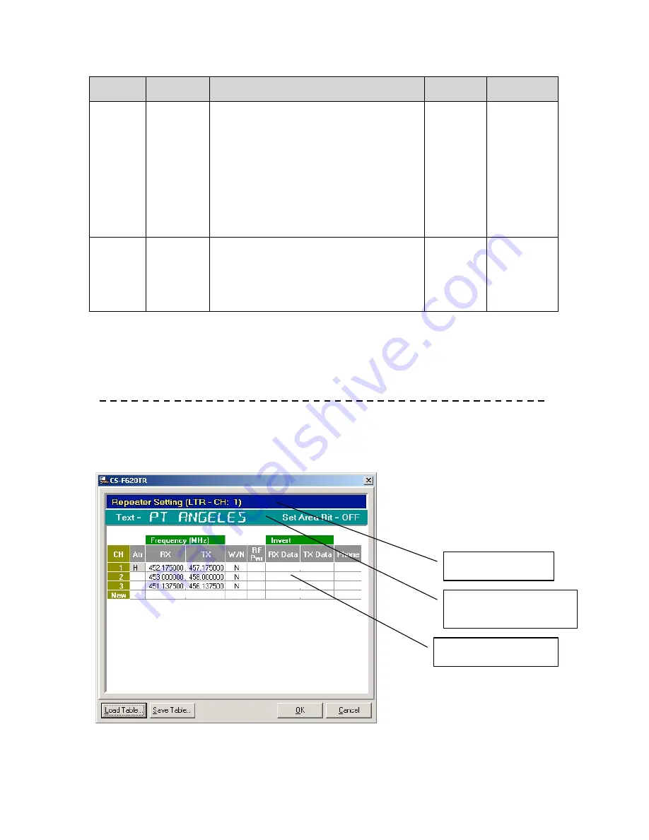
Mode and System
Indicator

Pertinent Text and Group
Detail from Parent
Programming Screen

Repeater Setting
Programming Sub-Screen

Summary of Contents for IC-F620

Page 1: ...CS F620 Programming Software Manual for Icom IC F620 F621TR ...

Page 2: ...ogramming Screen Detail 15 Memory CH Folder 16 Operation Programming Screen Field Description Table 17 PassPort Programming Screen 19 PassPort Programming Screen Field Description Table 19 PassPort Talk Group Setting Programming Sub Screen 27 PassPort Talk Group Setting Programming Sub Screen Field Description Table 28 LTR Programming Screen 30 LTR Programming Screen Field Description Table 30 Rep...

Page 3: ...reen 57 Set Mode Programming Screen Field Description Table 57 Common Programming Screen 59 Common Programming Screen Field Description Table 59 Timers Programming Screen 62 Timers Programming Screen Field Description Table 62 Trunking Features Programming Screen 64 Trunking Features Programming Screen Field Description Table 64 Field Data Programming Screen Field Description Table 66 Character Ed...

Page 4: ...of the IC 600 series transceivers the software generally included with this pdf file Icom part number CS F620TR This cloning software is used to retrieve edit and write radio configuration information to the IC F620 F621TR It is also used as well as to retrieve and save radio configuration information from or to the programming computer for archival purposes SOFTWARE COMPATIBILITY This software is...

Page 5: ...d in this manual CONNECTING RADIO Connect the 25 pin side of the OPC 1122 Connector to the programming laptop with the 25 to 9 pin serial cable provided in the programming cable kit Connect the microphone connector side of the OPC 1122 into the microphone jack of the radio Power the radio on MAIN SCREEN From this screen you can access all the functions of the software The screen contains five majo...

Page 6: ...ntroduction 3 The Toolbar provides quick access to commonly used functions The Tree Menu contains various Programming Screen Icons and folders that provide access to Programming Screens where you can read and edit detailed configuration information ...

Page 7: ... with a icf extension To start a new programming instance select New from the file menu To select Programming Screens go to the Tree Menu There you will see various Programming Screen Icons and folders folders contain icons that are broadly related Single clicking on an icon displays the programming screen associated with that icon To open a folder either double click on it or select the plus sign...

Page 8: ...he first system note the word New appears on the next line If you have another system you wish to enter after entering the first one enter it there LTR and PassPort programming screens follow the same pattern as the preceding Explore the other programming screens to set features as desired To write to a radio press the Clone Write button Yes the icon looks like a handheld and we re most definitely...

Page 9: ...CS F620TR Programming Software Manual rev 1 0 Programming Software in Detail 6 PROGRAMMING SOFTWARE IN DETAIL ...

Page 10: ...nfiguration file from the programming computers hard drive floppy drive etc File Save Save a radio configuration file to the programming computers hard drive floppy drive etc File Save As Save a radio configuration file to the programming computers hard drive floppy drive etc under a name different from the currently open file File Print Current Sheet Print current contents of programming screen W...

Page 11: ...umns visible in the programming screens requiring more scrolling Find the font size for you that offers the best compromise between legibility and amount of displayed information View Toolbar Select to display the toolbar or not Not displaying it achieves a small amount more of screen real estate at the expense of ease of use COM PORT MENU Contains selections pertaining to COM port utilization COM...

Page 12: ...selections for reading and writing to the IC F620 F621TR series radio Clone Read TR Read the configuration of a radio into the programming software Clone Write TR Write the configuration of a radio from the programming software to the radio Clone Information Read basic information concerning the attached radio including ESN serial number transceiver model revision comments and any installed option...

Page 13: ...sPort Only selection HELP MENU Allows selection of help this document and general version and registration information Help Contents Select this help document Help About CS F620TR Displays information concerning current software version and registration information as shown ...

Page 14: ...orrect data file usually with a icf extension Save Button Used to save configuration data to a file When selected use the dialog box that opens to name the file and store it in the folder of your choice Clone Read Used to read configuration information in an attached radio If you get a No answer from transceiver dialog box follow the onscreen recommendations Clone Write Used to write configuration...

Page 15: ...e purpose of keeping similar programming screen icons grouped together Collapsing a folder allows the user to de clutter the screen SPECIAL NOTES ON ALL PROGRAMMING SCREENS THE RED X The IC F620 F621TR programming software has a special feature that allows for fast diagnostics of configuration issues If there is a configuration problem in any of the programming screens a will be displayed over its...

Page 16: ... data choices in programming screen fields that have drop down selections This is a great way to speed up data entry RIGHT CLICK You can right click with your mouse on all of the fields of the programming screens Doing so usually brings up a small menu showing you the selections you have for that field or row THE WORD SYSTEM The PassPort LTR and Conv Conventional programming screens have a number ...

Page 17: ...Y FUNCTIONS AND PROGRAMMABLE KEYS The IC F620 F621TR has a number of programmable keys on the radio and on the optional HM 100TN DTMF microphone Key Functions can be assigned to any of those keys as described in the Key and Display Assign programming screen section starting on page 52 In this document it assumed that when discussing something like pressing the Priority key that a Priority key has ...

Page 18: ... Selecting this icon will display description and revision information in the programming screen This icon is a folder also and opening it will display the next level of icons and folders Don t let the LTR PassPort description here confuse you you can still add edit and delete Conventional system information from the icons inside this folder ...

Page 19: ...ain branch of the Tree Menu This folder is used to group all programming screen icons having to do with the configuration of each system in the IC F620 621TR Use this to access and edit detailed information concerning each system in the radio and setting system order on the channel selection buttons ...

Page 20: ...the System Type or Text field and selecting Up or Down Note you cannot add a system from here To add a system use the programming screen icon of the mode you desire also located in the Memory CH folder OPERATION PROGRAMMING SCREEN FIELD DESCRIPTION TABLE Field Description Default Suggested Settings CH The channel number and order of each system in the radio No user entry No user entry System Type ...

Page 21: ...en done editing in this programming screen you can proceed to other programming screens save your programming parameters to a file or proceed to writing the information to the radio assuming that editing has been finished for all other required programming screens also ...

Page 22: ...a into any other field besides the Text field the program will re direct the user back to the Text field automatically until data has been entered there Finally note that to delete a system you can right click on almost any field in the programming screen and select Delete from the menu that appears PASSPORT PROGRAMMING SCREEN FIELD DESCRIPTION TABLE Group Field Description Default Suggested Setti...

Page 23: ...o 10 characters for this field Mandatory field set as needed You cannot enter any other information on this row until data for this field has been entered TG Talk Group This field indicates the current number of Talk Groups and Select Call MINs programmed into this system Also this field can be double clicked to open the PassPort Talk Group Setting programming sub screen where Talk Group and MIN i...

Page 24: ...ies it is designed for This is the backup home channel that your radio will search for and use in case of failure of the primary home channel This is not supported in NTS Firmware from at least 2 4 earlier Blank Currently not supported in PassPort do not use Digital Color Code Select 0 1 2 or 3 It is unimportant what this is set to if Fixed DCC is set disable 3 System operator provided Digital Fix...

Page 25: ... function may allow a radio to find the best site for a given area Disabling this function allows the radio to discover a good enough site for an area Disable usually provides quicker searches Disable Blank Set as needed Generally this should be set to Enable Home System Look Back Select Enable or Disable Selecting Enable will force the radio to look back to its home system at an interval set by t...

Page 26: ...will reference back to when initiating a search AFTER SEARCHING NEAR SITES In other words if this setting is set to 3 then the radio will search the near sites a few times first Then it will go to this list and search the neighbor list of the past three sites while in roam mode If each list has 5 frequencies the limit in them then the radio could potentially search 15 frequencies while roaming As ...

Page 27: ... from 0 to 255 The Look Back field must be enabled for this field to matter As the radio looks back at its home site it must see an RSSI of this value or more before it attempts registration 0 Set as needed A good value to work with is 35 Setting this value even higher than Preferred will ensure that the Look Back function will work with less frustration for the user RSSI Condition Los Time Enter ...

Page 28: ...TOT Set to OFF manually type the word in or enter from 0 to 255 seconds Setting this prevents the radio from transmitting for a period longer than this timer OFF Set as needed Talk Around Select to None or any of the Conventional or LTR systems that appear in this list This is the system reverted to if the Talk Around key has been pressed If None is selected here and the Talk Around key is pressed...

Page 29: ...cled or the system is changed Disable Blank Set as needed DTMF Decode ch Select None or any of the DTMF Decode Pri Codes listed If a DTMF Decode Pri Code has been selected the radio will emit a ring tone and flash a bell icon if the proper DTMF sequence of digits is received You must set up a DTMF decode entry to use this function see the DTMF Decode programming screen page 48 If the Select Call k...

Page 30: ...n Don t be confused while this screen seems oriented around talk groups this is also where MINs and their MIN aliases can be entered to use for selective call The group tag you give to a MIN here will also act as a MIN Alias meaning when a MIN from a calling party matches a MIN entered here its group tag text rather than the MIN number will be displayed At the head of this screen is pertinent info...

Page 31: ...e only Depending on where the Group ID Start field is set and what information is entered into the RX ID field this will appear as either GRP or MIN This field will display GRP when the number entered in the RX ID field is at or greater than the Group ID Start When the number in the RX ID field is less than the Group ID Start this field will appear as MIN No user entry No user entry RX ID Enter fr...

Page 32: ...Select Yes or No When Type is GRP select whether you wish the group to be scanned by default when the radio is doing group scan You cannot edit this field if Type is MIN Yes if RX ID is a group number otherwise No Set as needed When finished editing here select OK to save the information entered here Select cancel to discard any edits ...

Page 33: ...o any other field besides the Text field the program will re direct the user back to the Text field automatically until data has been entered there Finally note that to delete a system you can right click on almost any field in the programming screen and select Delete from the menu that appears LTR PROGRAMMING SCREEN FIELD DESCRIPTION TABLE Group Field Description Default Suggested Settings CH The...

Page 34: ... Priority key is programmed Set as needed Text Double click here to enter a text description for this system as described on page 13 You can enter up to 10 characters for this field Mandatory field set as needed You cannot enter any other information on this row until this field has been filled in Repeater Repeater ch The number in this field indicates the row the current home channel repeater is ...

Page 35: ...he home channel is allowed None Blank Consult your system operator ATB Ring Back Select Enable or Disable If a user attempts to transmit and the system is busy enabling this will sound a ringing tone when the system is ready to accept traffic again Enable Blank Set as needed Scan Scan Enable Select Enable or Disable Selecting Enable will allow this system to be scanned when performing system scan ...

Page 36: ...s needed Scan Save User Settings Select Enable or Disable Allows user s changes to the systems being scanned to be saved when the radio s power is cycled or the system is changed Disable Blank Set as needed Scan Edit TG List Select Enable or Disable Allows user to manually edit the groups being scanned These edits are normally lost if the user changes groups or cycles power to the radio though not...

Page 37: ...s needed Scrambler Code Set from 1 to 255 With the UT 109 Non Rolling type only the value 1 through 32 will work With the UT 110 Rolling type values from 1 to 255 will work 1 Set the code number to match the code used by the customer in general When done editing in this programming screen you can proceed to other programming screens save your programming parameters to a file or proceed to writing ...

Page 38: ...Until one of the repeater channel rows is selected as a home repeater For each row there after this field will be blank Mandatory field for one of the rows You will get a in each Atr row until you select one of the rows as the home repeater That will clear the in all rows Consult your LTR system operator for information on which repeater channel is home Frequency RX Enter from 1 000000 to 520 0000...

Page 39: ...edits LTR TALK GROUP SETTING PROGRAMMING SUB SCREEN Double click on the Talk Group field of the LTR programming screen to enter the Talk Group Setting programming sub screen At the head of this screen is pertinent information concerning the current selected system Each line in this screen can be used to enter group information Note that to delete a row you can right click on almost any field in th...

Page 40: ...field will show a indicating that the contents of the TX ID field is the same as the RX ID field You can change this field to be different from the RX ID field for special purposes Until data is entered in the RX ID field This field then changes to Mandatory field normally leave as set after data has been entered in the RX ID field System operator provided Scan Member Select Yes or No Determines i...

Page 41: ...to any other field besides the Text field the program will re direct the user back to the Text field automatically until data has been entered there Finally note that to delete a system you can right click on almost any field in the programming screen and select Delete from the menu that appears CONVENTIONAL PROGRAMMING SCREEN FIELD DESCRIPTION TABLE Group Field Description Default Suggested Setti...

Page 42: ... as a priority system Otherwise Phone OFF Blank Mandatory field Amongst the programming screens for PassPort LTR and Conventional at least one system needs to be set as a priority system even if no Priority key is programmed Set as needed Frequency RX Enter from 1 000000 to 520 000000 though of course the radio will only function for frequencies it is designed for This is the radio receive frequen...

Page 43: ...nventional repeaters Off Blank Set as needed When working with Conventional Repeaters consult the system operator Text Double click here to enter a text description for this system as described on page 13 You can enter up to 10 characters for this field Mandatory field set as needed You cannot enter any other information on this row until this field has been filled in RF Pwr Select High or Low Spe...

Page 44: ...anned when performing system scan Selecting Disable will prevent this system from being scanned Even if the User Edit field is set to Enable the user will not be able to add this system to the list of systems scanned if Disable is selected in this field Enable Blank Set as needed Scan User Edit Set to Enable or Disable Allows user to manually add or delete this system from the list of systems to b...

Page 45: ...Set from 1 to 255 With the UT 109 Non Rolling type only the value 1 through 32 will work With the UT 110 Rolling type values from 1 to 255 will work 1 Set the code number to match the code used by the customer in general When done editing in this programming screen you can proceed to other programming screens save your programming parameters to a file or proceed to writing the information to the r...

Page 46: ...imes it is more useful to hard code some frequencies in this seed list to make likelihood of finding a system more certain particularly on large PassPort systems with many sites Consult your system operator for more information on whether frequencies are required to be entered here Be careful though these frequencies are not dynamic like neighbor frequencies and any change in a PassPort system hom...

Page 47: ...t as needed Note any frequencies programmed here should be home channels if the PassPort system is not setup for re direct and should be collect channels if the PassPort system is setup for re direct When done editing in this programming screen you can proceed to other programming screens save your programming parameters to a file or proceed to writing the information to the radio assuming that ed...

Page 48: ... ASID number Note that to delete an ASID Text alias you can right click on almost any field in the programming screen and select Delete from the menu that appears ASID TEXT PROGRAMMING SCREEN FIELD DESCRIPTION TABLE Field Description Default Suggested Settings No The total number of lines displayed will indicate the number of ASID Text Aliases entered You can have a maximum of 10 before getting an...

Page 49: ...are Manual rev 1 0 DTMF Autodial Folder 46 DTMF AUTODIAL FOLDER Located in the main branch of the Tree Menu Folder used to group all programming screen icons having to do with the DTMF encode and DTMF decode in the IC F620 621TR ...

Page 50: ...Description Default Suggested Settings No The line number of the DTMF Encode entry You can have up to 10 entries here before getting an overflow error No user entry No user entry Atr Select Emergency or Emergency OFF or Return to exit without selecting a new setting Selecting Emergency sets this system as the one to be used if the Emergency key has been pressed Note changing this field to Emergenc...

Page 51: ...ten used as control codes and it is sometimes useful to have special control over their tone duration 1 Set as needed Timer Digit time Enter from 0 to 32 767 in seconds Sets period of time in which the each digit of the DTMF sequence will sound other than Special Digit or First Digit 1 Set as needed Timer Inter Digit Enter from 0 to 255 in seconds Sets period of time between the sounding of each D...

Page 52: ...m as described on page 13 You can enter up to 10 characters for this field Blank Set as needed Primary Code Enter up to 10 numbers here This is the sequence of DTMF digits that is the primary decode for this row Blank Set as needed Primary Response Select None or any listed entry you must have entries in the DTMF Encode programming screen to see a list of selections here This is the DTMF response ...

Page 53: ...d Data programming screen on power up if it is in stun mode Blank Set as needed Dead Beat Response Select None or any listed entry you must have entries in the DTMF Encode programming screen to see a list of selections here This is the DTMF response given upon the proper decode of the digits in the Dead Beat Disable Code field None Set as needed Idle Reset Enter from 1 to 32 767 in seconds Time re...

Page 54: ...re Manual rev 1 0 Common Folder 51 COMMON FOLDER Located in the main branch of the Tree Menu Folder used to group all programming screen icons having to do with common and miscellaneous configurations used by the radio in general ...

Page 55: ... double click on the Assign field of the key you wish to re assign and select from the menu that appears Note all key functions can be assigned to any programmable key Please refer to the screen and table on page 53 for a list of all key functions that can be assigned to programmable keys Refer to previous screen shot 10 Key DTMF Mic Set to Enable or Disable Selecting enable allows for DTMF operat...

Page 56: ... These entries are listed numerically by their order of entry in the DTMF Encode programming screen DTMF Encode programming screen Select Call This is a DTMF function only Key assigned to this function will toggle Select Call On or Off When select call is On the radio is muted to dispatch traffic until a DTMF digit sequence that matches either the primary or secondary digit sequence of the DTMF en...

Page 57: ...es that the system or group is in the scan list No S icon indicates that it has been removed A blinking S indicates scan mode is active See the PassPort LTR and Conv programming screens Monitor Key assigned to this function will toggle the radio in and out of Monitor mode a Speaker Icon will be displayed when mode is enabled This disables CTCSS or DTCS tone code squelch Useful for monitoring frequ...

Page 58: ... and ZZ is the average RSSI value of last two received data messages The dash between YY and ZZ will turn to a when there is activity on the channel the radio is monitoring NA Mode Display Type Key assigned to this function will toggle the display type between Alpha and Scroll Select Alpha and the display will show the current system or talk group Select Scroll and the display will continuously sc...

Page 59: ...SI from the system This is useful if user will be using the radio in a localized area where if the radio were to go into search mode a better site would probably not be found This prevents the radio from being unnecessarily out of service Examples of where this could be handy would be at the fringe of the only site serving an area a tunnel or a localized area of blocking terrain The radio should b...

Page 60: ...sly Do not use Auto Auto Beep Select ON or OFF Selecting On will activate a short beep when keys are pressed Note some beeps such as the one for the lockout timer cannot be turned off ON Beep Level Select 1 through 5 or 1 Linked through 5 Linked Selecting 1 through 5 with 5 being the loudest will cause the beeps to sound at a constant volume regardless of the setting of the volume knob Selecting 1...

Page 61: ...for special purpose applications 300 3000Hz Mic Gain Select 1 Min through 5 Max Increases or decreases microphone gain for special purpose applications 3 When done editing in this programming screen you can proceed to other programming screens save your programming parameters to a file or proceed to writing the information to the radio assuming that editing has been finished for all other required...

Page 62: ...e contents of the radio by hooking up the target radio to the programming computer and selecting Clone Information from the main menu Blank Operational Setting Revert on Power UP Select Enable or Disable Selecting Enable sets the radio to always power up to the first system in the channel list see Operation programming screen Selecting Disable sets the radio to always power up to the last system s...

Page 63: ...the radio on start up to continuously scroll detailed information about the current PassPort LTR or Conventional system you have selected This can be over ridden by toggling the Mode Display Type key though if power is cycled the display will revert to Scroll Disable Option PassPort CRC LOS Tone Select Enable or Disable Selecting Enable causes the radio to emit a short tone whenever it goes into s...

Page 64: ...r as long as 4 4 seconds For LTR or Passport Continuous must be selected here though with Continuous mode the radio may experience occasional garble during voice transmissions Standard Scrambler Tone Start Timing Select Off 300ms 600ms 1100ms This setting is for the UT 110 only and only if the Synchronous Capture field is set to Standard Sets the sync tone delay OFF When done editing in this progr...

Page 65: ...l of time between when the activity goes away and scan resumes 2 000 Scan Delay Timers Group Revert Enter from 0 to 10 seconds If the radio in group scan stops on an active group this is the interval of time between when the activity goes away and the radio reverts back to the currently selected group for transmit purposes In other words this is the amount of time you have to reply back to a scann...

Page 66: ...io from transmitting for a period longer than this timer 30 000 Timeout Timers TOT Phone TX TOT Set to OFF manually type the word in or enter from 0 to 255 seconds Setting this prevents the radio from transmitting on an interconnected system for a period longer than this timer 180 000 Timeout Timers TOT Time Out Pre Alert Enter from 1 to 18 seconds This sets the period of time before the Time Out ...

Page 67: ...assPort Features Handshake Melody Select from various radios tones in menu This is the tone used for each transmission when handshaking with a PassPort system PassPort Handshake PassPort Handshake PassPort Features Handshake Retry Limit Enter from 0 to 255 This is the number of times a handshake will be attempted with a PassPort system until a Busy tone is emitted from the radio The user at this p...

Page 68: ...it is currently registered to and when it will go into search roam mode 30 000 20 Other Time Select System Roam Delay Enter from 2 to 250 After a new system is selected this is the amount of time the radio will wait until initiating search roam mode 11 000 7 Other Time Roaming Wait Select from 2 to 65 535 If a radio is in search roam mode this is the amount of time the radio will wait on each freq...

Page 69: ... the radio is first powered on You can enter up to 10 characters here HELLO Text Stun Text Double click here as described on page 13 and enter the text you wish to have displayed if the radio has been stunned PassPort or DTMF stun You can enter up to 10 characters here STUNNED Text Kill Text Double click here as described on page 13 and enter the text you wish to have displayed if the radio has be...

Page 70: ...t the Odometer Write field of the Common programming screen has been set to Enable 0 00 00 No user entry Expert Field Serial Number Enter from 00000000 to 99999999 A user defined serial number can be entered here 00000000 Ignition SW Disable Select Enable or Disable Selecting Enable here will set the radio to power on automatically when the ignition switch is turned on Disable When done editing in...

Page 71: ...rs in the 16 fields here These characters can be used along with the default characters as the text to enter in the Text Dialog Box see page 13 To create or edit a custom character double click on one of the 16 new or existing fields in the Character Editor programming screen A dialog box will then be displayed that will allow you to edit segments Click on the segments in this screen to toggle the...

Page 72: ...reen 69 When done editing in this programming screen you can proceed to other programming screens save your programming parameters to a file or proceed to writing the information to the radio assuming that editing has been finished for all other required programming screens also ...

Page 73: ...CS F620TR Programming Software Manual rev 1 0 Appendix 70 Appendix ...

Page 74: ...ng Software Manual rev 1 0 APPENDIX A RSSI Reference Chart for Min and Preferred fields in the PassPort Programming Screen 71 APPENDIX A RSSI Reference Chart for Min and Preferred fields in the PassPort Programming Screen ...

Page 75: ...ous system scenarios The IC F620 F621TR series radio is highly versatile and is capable of far more functions than indicated here None the less the demonstrated configurations are a good starting point for configuring the radio for a variety of system protocols These can be a starting point for configuring a radio for each customer s or system operator s needs ...

Page 76: ... where this could be handy would be at the fringe of the only site serving an area a tunnel or a localized area of blocking terrain The radio should be removed from Site Lock mode as soon as possible to return to normal operation P1 Roam Request This will force the radio to go into search mode roam This is useful if the operator of the radio is having trouble with a system for example distant enou...

Page 77: ...r its Home Site or the site it was last registered to Searching Roam The radio go into search mode when one of several criteria are met When the radio has just been turned on When a new PassPort system is selected When the signal from the current site the radio is registered to becomes unusable for communications When the Roam Request key is activated Normally a site should be found within about 2...

Page 78: ...ou will hear a tone and be connected You can now have a private conversation with the person you are connected to without disturbing any dispatch group To disconnect a selective call press the Group MIN Up key You will hear a disconnect tone Note when using selective call the site s repeater that was setup for the selective call will stay up for the duration of the call This can be slightly discon...

Page 79: ...to scan or not scan Select the targeted group or system press and hold the Scan key down until you see SCAN ADD or SCAN DEL This adds or deletes the system or group from being scanned A steady S icon indicates that the system or group is in the scan list No S icon indicates that it has been removed A blinking S indicates scan mode is active P1 Nuisance Delete This is useful to temporarily remove n...

Page 80: ...the group if there is more than one group in the system Group Dispatch After the radio has registered it is normally ready to perform Group Dispatch To call a base unit or other field units simply press the PTT key Wait until you get the PTT handshake tone and then start speaking It is a common mistake for first time users to attempt to over talk this tone but after a couple of minutes of practice...

Page 81: ...g scanned A steady S icon indicates that the system is in the scan list No S icon indicates that it has been removed A blinking S indicates scan mode is active P1 Nuisance Delete This is useful to temporarily remove non essential systems from being scanned Cycling radio power or changing systems will clear this setting P2 Talk Around If the radio has another Conventional or LTR system programmed i...

Page 82: ...broadcast to one or more radios on the same frequency and using the same tone coded squelch if utilized Use with a Repeater If coded squelch is used on a repeater briefly press the Monitor key ensure that no one else is currently using the repeater the Monitor key disables the coded squelch enabling the user to hear all activity on the channel Then press the Push to Talk key to broadcast to other ...

Reviews: