background image

Icom, Icom Inc. and the Icom logo are registered trademarks of Icom Incorporated (Japan) in Japan, the United States, the 
United Kingdom, Germany, France, Spain, Russia and/or other countries.
Adobe and Adobe Reader are registered trademark of Adobe Systems Incorporated.
All other products or brands are registered trademarks or trademarks of their respective holders.

About these Advanced Instructions (PDF format)

These Advanced Instructions describe the details of the IC-7200 features. This PDF formatted manual provides you 
with convenient functions, as follows.

INTRODUCTION

Previous view

3-7

3

BASIC OPERATION

Frequency setting (Continued)


D

Quick tuning function

The operating frequency can be changed in steps of 
0.1, 1, 5, 9 or 10 kHz selectable for quick tuning.

 Push 


q

TS

 to turn ON the Quick tuning function.

Z

” appears.

 Rotate 


w

[DIAL]  to  change  the  frequency  in  pro-

grammed kHz steps.
 Push 


e

TS

 again to turn OFF the Quick tuning func-

tion.

Z

” disappears.

Rotate 


r

[DIAL] for normal tuning, if desired.


D

Selecting ‘kHz’ step

When the Quick tuning function is selected, the fre-
quency can be changed in the selected ‘kHz’ steps.
 • 


0.1, 1, 5, 9 or 10 kHz are selectable.

 Push 


q

TS

 to turn ON the Quick tuning function.

Z

” appears.

 Hold  down 


w

TS

  for  1  second  to  enter  the  tuning 

step Set mode.
 Rotate 


e

[DIAL] to select the desired tuning step of 

0.1, 1, 5, 9 or 10 kHz.
Push 


r

TS

 to exit the tuning step Set mode.

 Rotate 


t

[DIAL] to change the frequency according 

to the set tuning step.
 Push 


y

TS

 to turn OFF the Quick tuning function.

Z

” disappears.

[DIAL]

Appears

[DIAL]

Appears

Tuning step Set mode

Hold down 

TS

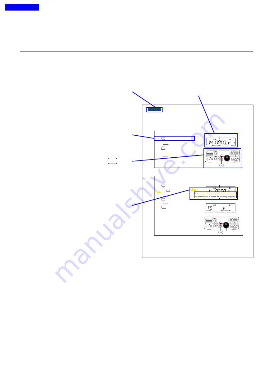
Move to the previously read page.

Click [Previous view] at the left top on an each page, to 
move back to the previously read page.

Shows a term description

When the mouse cursor is moved over a term which 
is highlighted in yellow, the description of the term is 
displayed.

Shows the location of keys

When the cursor is moved over a term with a red un-
derline,  a  red  circle  appears  around  the  appropriate 
key(s) on the figure of the transceiver.

The  screen  shots  at  the  right  column,  correspond  to 
the operating instructions and procedures shows both 
setting and operating example.

Example:  When the cursor is moved over 

TS

 in the 

description, a red circle appears around the 
appropriate key(s).

Previous view

Summary of Contents for IC-7200

Page 1: ...unction is selected the fre quency can be changed in the selected kHz steps 0 1 1 5 9 or 10 kHz are selectable Push q TS to turn ON the Quick tuning function Z appears Hold down w TS for 1 second to enter the tuning step Set mode Rotate e DIAL to select the desired tuning step of 0 1 1 5 9 or 10 kHz Push r TS to exit the tuning step Set mode Rotate t DIAL to change the frequency according to the s...

Page 2: ...en Click to open the find or search screen or advanced search screen Printing out the desired pages Click Print P in File menu and then select the pa per size and page numbers you want to print The printing setup may differ depending on the printer Refer to your printer s instruction manual for details Select A4 size to print out the page in the equal ized size Read Out Loud feature The Read Out L...

Page 3: ...TION INDEX 11 CONTROL COMMAND INDEX 10 SET MODE 9 ANTENNA TUNER OPERATION 8 SCAN OPERATION 7 MEMORY OPERATION 6 FUNCTIONS FOR TRANSMIT 5 FUNCTIONS FOR RECEIVE 4 RECEIVE AND TRANSMIT 3 BASIC OPERATION 2 INSTALLATION AND CONNECTIONS 1 PANEL DESCRIPTION INTRODUCTION ...

Page 4: ...14 15 16 17 18 19 20 21 1 1 Section 1 PANEL DESCRIPTION Front panel 1 2 Keypad D D 1 9 Function display 1 12 Rear panel 1 14 ACC socket information D D 1 16 Microphones 1 17 SM 50 Option D D 1 17 SM 30 Option D D 1 17 HM 36 D D 1 17 ...

Page 5: ...y turned ON In the noise blanker Set mode rotate M CH u to select the item then rotate DIAL to set What is the noise blanker The noise blanker reduces pulse type noise such as that generated by automobile ignition systems This function is not effective against non pulse type noise eNR KEY NR p 5 8 Push to turn the noise reduction function ON or OFF appears when the noise reduction function is ON H...

Page 6: ...equency re sponse tKEYPAD Push the keys to select various functions Details on each function are listed on page 1 9 After holding down F INP ENT BAND for 1 second push a key on the keypad to select the operating band p 3 4 After the band has been used once the last used fre quency is recalled when the band is selected again GENE selects the general coverage receive band After pushing F INP ENT BAN...

Page 7: ...ng the transmit frequency This is useful for fine tuning stations calling you off fre quency or when you prefer to listen to slightly different sounding audio characteristics About the M CH control activation RIT control indicator i as below Lights OFF icon 6 on page 1 13 Appears Acts as the RIT control Acts as the memo ry channel control Disappears N A iRIT CONTROL INDICATOR pp 5 2 7 2 Lights ora...

Page 8: ...d ON Hold down for 1 second to enter tun ing step Set mode After selecting a step push again to return to nor mal operation 0 1 1 5 9 and 10 kHz tuning steps are selectable While the Quick tuning function is turned OFF hold down for 1 second to turn the 1 Hz step ON or OFF 1 Hz indication appears and the frequency is changed in 1 Hz steps 1MODE KEY MODE p 3 11 Push to cycle through the operating m...

Page 9: ...old down the key again to return to normal operation 5SPCH LOCK KEY SPCH Push to announce the displayed frequency and S meter level by the speech synthesizer p 3 13 The items to be announced can be selected in the Set mode p 10 12 Hold down for 1 second to turn the Dial lock func tion ON or OFF p 3 12 The dial lock function electronically locks the main dial appears while the dial lock function is...

Page 10: ...AM SQL SQL RF GAIN SQL Minimum RF gain Adjustable range RF gain adjustable range Maximum RF gain Maximum RF gain Squelch is open S meter squelch S meter squelch threshold Lowest threshold Highest threshold Squelch is open S meter squelch S meter squelch threshold When functioning as the RF GAIN SQL control When functioning as the RF GAIN control Squelch is fixed open SSB CW RTTY only When function...

Page 11: ...hones are connected the speaker audio is disabled 1MICROPHONE CONNECTOR MIC Accepts the supplied or optional microphones See page 1 17 for appropriate microphones and micro phone connector information Front panel Continued i7200 MODE TUNER TS FILTER SPCH V M A B SPLIT M CL SCAN SET ATT P AMP COMP VOX MNF RIT 1 2 3 4 5 6 7 8 0 50 28 18 14 10 21 24 7 3 5 1 8 F INP M CH RIT ENT BAND GENE 9 AGC MW ANF...

Page 12: ...uency and operating mode are set to the same frequency and operating mode as the displayed VFO 2 3 5 Push F INP ENT BAND then push this key to input the number 2 p 3 6 Hold down F INP ENT BAND for 1 second then push this key to select the 3 5 MHz band p 3 4 4SPLIT 3 7 MHz BAND KEY SPLIT Push to turn the Split function ON or OFF p 6 8 appears when the split function is ON Hold down for 1 second to ...

Page 13: ...3 4 8SPEECH COMPRESSOR 7 21 MHz BAND KEY COMP Push to turn the Speech compressor function ON or OFF p 6 6 appears when the speech compressor func tion is ON Hold down for 1 second to enter the speech com pression level Set mode Rotate DIAL to set the compression level then push the key again to re turn to normal operation 7 21 Push F INP ENT BAND then push this key to input the number 7 p 3 6 Hold...

Page 14: ...ect the 50 MHz band p 3 4 2RIT GENERAL BAND KEY RIT Push to turn the RIT Receiver Incremental Tun ing function ON or OFF p 5 2 appears when the RIT function is ON The RIT frequency can be adjusted with the M CH control when the RIT mode is selected Hold down for 1 second to add the RIT shift fre quency to the operating frequency p 5 2 Selectable only when the XFC transmit frequency check function ...

Page 15: ...Y CHANNEL NUMBER READOUT p 7 2 Shows the selected memory channel number uBLANK ICON p 7 3 Appears when the selected memory channel is blank This icon appears in both the VFO and memory modes iS RF METER Displays the receiving signal strength Displays either the transmit power PO SWR or ALC while transmitting p 3 13 oNOTCH ICONS p 5 9 5 10 appears when the automatic notch func tion is ON appears wh...

Page 16: ... is ON in the SSB mode appears when the VOX function is ON appears when the Split function is ON appears when preamp is ON appears when the attenuator is ON appears during a scan Blinks when the scan is paused 9AGC ICONS p 5 3 Displays the selected AGC time constant F AGC for AGC fast AGC OFF for AGC OFF no icon for AGC slow 0BREAK IN ICONS BK appears when the Semi break in function is ON p 6 4 F ...

Page 17: ...SOCKET ACC Enables connection to external equipment such as a TNC for data communications a linear amplifier or an automatic antenna tuner and so on See below for socket wiring information tELECTRONIC KEYER JACK KEY Accepts a key or paddle connector for the internal electronic keyer The keyer type selection between the internal electronic keyer and straight key operation can be made in the Set mod...

Page 18: ...nternal speaker is disabled 1USB JACK Connects a USB cable for transceiver modulation input p 2 9 the transceiver operation with a PC and the received audio sent to the PC CAUTION The USB driver must be installed Please read the USB driver installation guide before installing the USB driver into your PC that is connected to the IC 7200 with the USB cable third party Rear panel Continued About the ...

Page 19: ...hen power is ON Output current Max 1 A 9 KEY Key line for the optional AT 180 10 FSKK Controls RTTY keying High level Low level Output current More than 2 4 V Less than 0 6 V Less than 2 mA 11 MOD Modulator input Input impedance Input level 10 k Approx 100 mV rms 12 AF AF detector output Fixed level regardless of the AF con trol position Output impedance Output level 4 7 k 100 300 mV rms 13 SQLS S...

Page 20: ...y paddle Pre set in the Set mode U D KEY Mic Up Down Keyer p 10 15 r LOW CUT SWITCH Only for the SM 50 and SM 30 Push SM 50 Slide SM 30 to cut out the low fre quency components of input voice signals t PTT LOCK INDICATOR LOCK Only for the SM 30 Lights red when the PTT lock switch e is ON y MIC GAIN VOLUME MIC GAIN Only for the SM 50 and SM 30 Rotate to adjust the microphone output level Use this c...

Page 21: ...ophone ground MIC PIN NO FUNCTION DESCRIPTION w 8 V DC output Max 10 mA e Frequency up Ground Frequency down Ground through 470 r Squelch open LOW level Squelch close HIGH level CAUTION DO NOT short pin 2 to ground as this can damage the internal 8 V regulator DC voltage is applied to pin 1 for microphone operation Use caution when using a non Icom microphone Microphones Continued Previous view ...

Page 22: ...r supply connections 2 5 Connecting the DC Power Supply 2 5 Battery connections 2 6 External antenna tuners 2 6 Connecting a linear amplifier 2 7 Connecting a CW keyer 2 8 Connecting a PC TNC for RTTY 2 9 Connections for RTTY FSK D D 2 9 Connections for RTTY AFSK D D 2 9 Connecting a PC TNC for SSTV or PSK31 2 10 Connecting to the ACC socket D D 2 10 Connecting to the MIC connector D D 2 10 Connec...

Page 23: ... GND terminal to a gas or electric conduit since the con nection could cause an explosion or electric shock GND Connecting an antenna For radio communications the antenna is of critical importance for output power and sensitivity Use well matched 50 ø antennas and coaxial feedline An SWR standing wave ratio of 1 5 1 or lower is recommend ed when transmitting CAUTION Protect your transceiver from l...

Page 24: ...p 2 2 Use the heaviest gauge wire or strap available and make the connection as short and straight as possible Grounding prevents electrical shocks TVI and other prob lems CW KEY A straight or bug key can be used when the internal electronic keyer is turned OFF in the Set mode p 10 15 HF 50 MHz ANTENNA DC POWER SUPPLY p 2 5 PS 126 Previous view ...

Page 25: ... The AFSK modulation signal can be input from MIC p 2 9 Rear panel ACC SOCKET p 1 16 AH 4 p 2 6 AH 2b or long wire with EXTERNAL SPEAKER REMOTE p 11 2 Used for computer control and transceive operation SEND ALC p 2 7 Used to connect to a non Icom linear amplifier SP 34 option Previous view ...

Page 26: ...A DC power supply AC outlet AC cable 30 A fuses Supplied DC power cable 13 8 V at least 22 A Black _ Red Transceiver To DC power socket To DC power socket CAUTION The rear panel will become hot when continu ously operating the trans ceiver for long periods CAUTION The rear panel will become hot when continu ously operating the trans ceiver for long periods CONNECTING A NON ICOM DC POWER SUPPLY DC ...

Page 27: ...t or receive audio Use a rubber grommet when passing the DC power cable through a metal plate to prevent a short circuit The IC 7200 is not certified for vehicle installation in European countries Grommet CONNECTING A VEHICLE BATTERY Note Use terminals for the cable connections Crimp Solder Supplied DC power cable red black 12 V battery External antenna tuners CONNECTING an AH 4 Ground Ground Long...

Page 28: ...ING Set the transceiver output power and linear am plifier ALC output level by referring to the linear amplifier instruction manual Be sure the linear amplifier keying circuit control voltage is compat ible with the IC 7200 before connecting to the SEND connector The ALC input level must be in the range 0 V to 4 V and the transceiver does not accept posi tive voltage Non matched ALC and RF power s...

Page 29: ...Connect an external switch such as a foot switch or use the RTTY SEND terminal for all bands p 2 9 See page 10 17 for connection details Connect a paddle to the MIC connector Bug Reverse Normal Mic Up Down keyer ON Keyer type Straight key Keyer type Bug key Paddle polarity Reverse Paddle polarity Normal When connecting an external electronic keyer set the keyer type to St straight key Previous vie...

Page 30: ...required SQL light green FSKK black AF out light blue SEND orange GND red TNC or PC interface for the RTTY software Colors refer to the wires in the supplied ACC cable GND AF 2 conductor 1 8 plug D D Connections for RTTY AFSK MIC Front panel i AF out PC Connect SQL line when required TNC or PC interface for the RTTY software r SQL t PTT y GND u GND q MIC Front panel view Previous view ...

Page 31: ...ware Colors refer to the wires in the supplied ACC cable Rear panel view D D Connecting to the MIC connector MIC Front panel i AF out PC Connect SQL line when required TNC or PC interface for the software r SQL t PTT y GND u GND q MIC Front panel view D D Connecting to the USB jack Connect an USB cable third party s between the transceiver s USB jack and PC p 1 15 The USB driver and the installati...

Page 32: ...pad D D 3 6 Quick tuning function D D 3 7 Selecting kHz step D D 3 7 Selecting the 1 Hz and 10 Hz tuning steps D D 3 8 TS D D switch flow chart 3 8 Selecting the Auto tuning step D D 3 9 Using the D D tuning function SSB data CW RTTY only 3 9 Setting the Band edge warning beep D D 3 10 About the 5 MHz band operation USA version only D D 3 10 Selecting the operating mode 3 11 Adjusting the audio vo...

Page 33: ...VFO operation Selecting the VFO A or B D D Push A B to select either VFO A or VFO B Hold down A B for 1 second to set the undisplayed VFO frequency and mode to the displayed VFO frequency and mode 3 beeps sound when the VFO equalization is complet ed CONVENIENT Use the two VFOs as quick memories When you find a new station but you wish to con tinue searching the two VFO systems can be used for qui...

Page 34: ...ncy or mode is changed the memory channel does not memorize the new frequency or operating mode Even if the frequency and mode are changed in the memory then another memory or VFO is selected when the first memory is selected again its original programmed frequency and mode appear EXAMPLE Chan memo VFO is selected The frequency is changed VFO is selected again Changed frequency 14 123 MHz appears ...

Page 35: ...MHz 21 200000 MHz USB 3 5 MHz 3 550000 MHz LSB 24 MHz 24 950000 MHz USB 7 MHz 7 050000 MHz LSB 28 MHz 28 500000 MHz USB 10 MHz 10 120000 MHz CW 50 MHz 50 100000 MHz USB 14 MHz 14 100000 MHz USB General 15 000000 MHz USB 18 MHz 18 100000 MHz USB D D Using the band stacking register Band keys Example Selecting the 14 MHz band Hold down q q F INP ENT BAND for 1 second to enter the band selection mode...

Page 36: ...second push the desired band key to select the corresponding band When you push GENE the general coverage receiver mode is selected Rotate w w DIAL to set the desired frequency NOTE If the dial lock function is ON lock icon appears and DIAL is disabled Hold down SPCH for 1 second to turn the dial lock function ON or OFF see p 3 12 for details Band keys DIAL 21 MHz band is selected Previous view ...

Page 37: ...h e e F INP ENT BAND to set the input frequency To cancel the input push M CH RIT SET or any key except a keypad key 21 280 MHz 21 245 MHz 14 025 MHz EXAMPLE 706 kHz MNF 0 50 M CL 5 14 COMP 7 21 SCAN 8 24 SPLIT 3 7 A B 2 3 5 F INP ENT BAND VOX 28 9 RIT GENE 6 18 AGC 4 10 MW V M 1 1 8 F INP ENT BAND F INP ENT BAND RIT GENE F INP ENT BAND F INP ENT BAND 4 10 MW V M 1 1 8 RIT GENE MNF 0 50 M CL 5 14 ...

Page 38: ...red D D Selecting kHz step When the Quick tuning function is selected the fre quency can be changed in the selected kHz steps 0 1 1 5 9 or 10 kHz are selectable Push q q TS to turn ON the Quick tuning function Z appears Hold down w w TS for 1 second to enter the tuning step Set mode Rotate e e DIAL to select the desired tuning step of 0 1 1 5 9 or 10 kHz Push r r TS to exit the tuning step Set mod...

Page 39: ... 10 Hz step settings When the 1 Hz step is selected the 1 Hz digit appears in the frequency display when the 10 Hz step is selected the 1 Hz digit disappears from the frequency display Rotating DIAL changes the frequency in 1 Hz or 10 Hz tuning step DIAL Hold down for 1 second Rotating DIAL changes the frequency in 10 Hz steps Rotating DIAL changes the frequency in 1 Hz steps TS Appears 10 Hz tuni...

Page 40: ...uning step is turned OFF Hold down M CL for 1 second to select a default option or value Push r r M CH RIT SET to exit the Set mode While operating in SSB data CW RTTY the tuning function can be used for critical tuning Dial sensitivity is reduced to of normal when the function is in use Hold down q q M CH RIT SET for 1 second twice to enter the Set mode Rotate w w M CH to select DIAL Rotate e e D...

Page 41: ...ions may use these frequencies NOTE We recommend that you store these fre quencies modes and filter settings into memory channels for easy recall To assist you in operating within the rules specified by the FCC transmission is illegal on any frequen cies other than the five shown in the tables to the right For the USB and USB Data modes The FCC specifies center frequencies on the 5 MHz frequency b...

Page 42: ... desired operating mode cannot be se lected it may be disabled in the Set mode p 10 16 Selecting the operating mode DIAL M CH q Push MODE to select the SSB or AM mode After the SSB mode is selected hold down MODE for 1 second to toggle between the USB and LSB modes w Hold down M CH RIT SET for 1 second to enter the Quick Set mode e Rotate M CH to select DATA to set the data mode r Rotate DIAL to t...

Page 43: ...Receive sensitivity Normally the RF SQL control is set to the 12 o clock position Rotate the RF SQL control to the 11 o clock position for maximum sensitivity Rotate the RF SQL control clockwise to increase the re ceiver sensitivity counterclockwise to decrease it The S meter indicates receive sensitivity Adjusting the squelch Removing non signal noise Rotate the RF SQL control to the 1 o clock po...

Page 44: ...meter movement shows the input signal level exceeds the allowable level the ALC lim its the RF power In such cases reduce the MIC gain setting see page 3 14 in the Quick Set mode Using the Voice synthesizer function The IC 7200 has a voice synthesizer This function announces the S meter level operating frequency and mode in a clear electronically generated voice in English or Japanese NOTE The S m...

Page 45: ... W Carrier power Microphone gain setting Microphone gain must be adjusted properly so that your signal does not distort when transmitted Select the SSB or AM mode q q Hold down w w ANF METER for 1 second one or more times to select the ALC meter Hold down e e M CH RIT SET for 1 second to enter the Quick Set mode Rotate r r M CH to select MIC GAIN Push t t PTT to transmit Speak into the microphone ...

Page 46: ...D 4 7 Selecting the CW R CW reverse mode D D 4 8 Adjusting the CW tone pitch control D D 4 8 Adjusting the CW side tone D D 4 9 Setting Keying speed D D 4 9 Operating in the RTTY FSK mode 4 10 Convenient functions for receiving D D 4 10 Selecting the RTTY R RTTY reverse mode D D 4 12 Selecting the Twin peak filter D D 4 12 RTTY decode Set mode D D 4 13 Operating in the AM mode 4 14 Convenient func...

Page 47: ...ntrol to set audio to a comfort able listening level Push t t PTT to transmit appears Speak into the microphone at your normal voice y y level Adjust MIC Gain at this step if necessary p 10 4 Release u u PTT to receive D D Convenient functions for receiving Preamp and attenuator p 5 3 Push P AMP ATT to turn the preamp ON or OFF appears when the preamp is ON Hold down P AMP ATT for 1 second to turn...

Page 48: ...hold level or the blank width Noise reduction p 5 8 Push NR to turn the noise reduction ON or OFF appears when the noise reduction is ON Hold down NR for 1 second to enter the noise reduction level Set mode then rotate DIAL to ad just the noise reduction level Manual notch filter p 5 10 Push MNF to turn the manual notch filter ON or OFF appears when the manual notch filter is ON Hold down MNF for ...

Page 49: ...N Hold down VOX for 1 second to enter the VOX Set mode then rotate DIAL to adjust the VOX gain anti VOX gain and VOX delay Rotate M CH to select an item Speech compressor p 6 6 Push COMP to turn the speech compressor ON or OFF appears when the speech compressor is ON Hold down COMP for 1 second to enter the com pression level Set mode then rotate DIAL to ad just the compression level DIAL M CH DIA...

Page 50: ...onic keyer to send your CW signals appears The Po meter displays the transmit output power Stop keying to receive i i Band keys DIAL AF CW or CW R appears M CH Semi break in default OFF 7 5 dots default q Hold down M CH RIT SET for 1 second twice to enter the Set mode w Rotate M CH to select BK IN to set the CW break in mode e Rotate DIAL to select full break in semi break in or OFF FL full break ...

Page 51: ... appears when the fast time constant is select ed and no icon appears when the slow time constant is selected Hold down AGC for 1 second to turn OFF the AGC function AGC OFF appears Noise blanker p 5 7 Push NB to turn the noise blanker ON or OFF appears when the noise blanker is ON Hold down NB for 1 second to enter the noise blanker Set mode Rotate M CH to select the item then rotate DIAL to adju...

Page 52: ...cond to enter the Quick Set mode Rotate w w M CH to select CW PITCH Rotate e e DIAL to set the desired CW tone pitch to between 300 to 900 Hz in 10 Hz steps Push r r M CH RIT SET to exit the Quick Set mode DIAL DIAL M CH DIAL M CH Break in function p 6 4 Hold down q q M CH RIT SET for 1 second twice to enter the Set mode Rotate w w M CH to select BK IN Rotate e e DIAL to set the CW break in to ful...

Page 53: ...e received CW tone pitch and monitored CW tone pitch can be adjusted to between 300 and 900 Hz without changing the operating frequency q qWhen the CW or CW R mode is selected hold down M CH RIT SET for 1 second to enter the Quick Set mode Rotate w w M CH to select CW PITCH then rotate DIAL to adjust to the desired tone pitch The CW tone pitch is adjusted to between 300 and 900 Hz in 10 Hz steps P...

Page 54: ...r 1 second to enter the Quick Set mode Rotate w w M CH to select SIDE LVL then rotate DIAL to adjust the side tone level Adjust the side tone level to between 0 and 100 in 1 steps Push e e M CH RIT SET to exit the Quick Set mode DIAL M CH D D Setting Keying speed The transceiver s internal electronic keyer speed can be set to between 6 and 60 words per minute wpm q qWhen the CW or CW R mode is sel...

Page 55: ...nnot be demodulated try se lecting the opposite mode RTTY or RTTY R Transmit a SEND signal from your PC or terminal r r appears The PO meter displays the transmitted output power Use the PC or TNC TU to transmit RTTY FSK t t signals Band keys DIAL RTTY or RTTY R appears Appears while transmitting D D Convenient functions for receiving Preamp and attenuator p 5 3 Push P AMP ATT to turn the preamp O...

Page 56: ...ate DIAL to adjust the threshold level or the blank width Noise reduction p 5 8 Push NR to turn the noise reduction ON or OFF appears when the noise reduction is ON Hold down NR for 1 second to enter the noise reduction level Set mode then rotate DIAL to ad just the noise reduction level Manual notch filter p 5 10 Push MNF to turn the manual notch filter ON or OFF appears when the manual notch fil...

Page 57: ...2125 Hz 170 Hz 2125 Hz BFO Mark Space Displayed frequency Displayed frequency Mark Space D D Selecting the Twin peak filter The twin peak filter changes the receive frequency re sponse by boosting two particular frequencies 2125 and 2295 Hz for better copying of desired RTTY sig nals Push q q MODE to select RTTY mode Hold down MODE for 1 second to toggle between the RTTY and RTTY R modes Hold down...

Page 58: ...fault value Push r r M CH RIT SET to exit the Quick Set mode DIAL M CH RTTY mark tone RTTY mode This item selects the RTTY mark frequency Select 1275 1615 or 2125 Hz RTTY shift width RTTY mode This item adjusts the RTTY shift width There are 4 selectable values 170 200 425 and 850 Hz RTTY key polarity RTTY mode This item selects the RTTY keying polarity Normal or reverse keying polarity can be sel...

Page 59: ...sary p 10 4 Release u u PTT to receive D D Convenient functions for receiving Preamp and attenuator p 5 3 Push P AMP ATT to turn the preamp ON or OFF appears when the preamp is ON Hold down P AMP ATT for 1 second to turn ON the at tenuator appears when the attenuator is ON Push P AMP ATT to turn OFF the attenuator Twin PBT passband tuning p 5 4 Rotate TWIN PBT controls inner outer AGC auto gain co...

Page 60: ... to ad just the noise reduction level Manual notch filter p 5 10 Push MNF to turn the manual notch filter ON or OFF appears when the manual notch filter is ON Hold down MNF for 1 second to enter the manual notch filter Set mode then rotate DIAL to select the narrow mid or wide filter width Auto notch filter p 5 9 Push ANF METER to turn the auto notch filter ON or OFF appears when the auto notch fi...

Page 61: ...ta mode adjust the AF output level from PC so that the ALC meter reading stays within the ALC zone NOTE When the data mode is selected the audio input from the ACC connector is used for trans mission instead of the MIC connector The speech compressor is turned OFF in the SSB data mode The desired connector can be selected in the Set mode p 10 11 For your information The carrier point frequency is ...

Page 62: ...5 4 Selecting the IF filter 5 5 IF filter selection D D 5 5 Setting the passband filter width D D 5 6 Selecting IF filter shape SSB CW only D D 5 6 Activating the Noise blanker 5 7 Setting the noise blanker level and width D D 5 7 Activating the Noise reduction function 5 8 Setting the noise reduction level D D 5 8 Activating the Notch filters 5 9 Auto notch filter D D 5 9 Manual notch filter D D ...

Page 63: ...transmit frequency Push q q RIT to turn ON the RIT function and the frequency shift are displayed The frequency shift is displayed for approximately 1 second then returns to the operating frequency The RIT control indicator lights orange If the RIT control indicator does not light push M CH RIT SET See below for details Rotate the w w M CH control to compensate for off frequency stations The trans...

Page 64: ...nuator Push P AMP ATT turn OFF the attenuator appears when the 20 dB attenuator is ON NOTE Only one of these functions can be acti vated at a time Either or appears Push Push Hold down for 1 second P AMP ATT ON OFF P AMP ATT OFF OFF P AMP ATT OFF ON Hold down for 1 second Push AGC function The AGC automatic gain control controls receiver gain to produce a constant audio output level even when the ...

Page 65: ... is half of the passband width and PBT is adjustable in 200 Hz AM or 50 Hz other models steps PBT OPERATION EXAMPLE IF center frequency Interference Desired signal Passband Both controls at center position Cutting the lower passband Cutting both higher and lower passbands Interference Interference Desired signal Passband TWIN PBT TWIN PBT TWIN PBT The TWIN PBT controls should normally be set to th...

Page 66: ...n 50 and 2700 Hz in 50 or 100 Hz steps A total of 32 passband widths can be set For the AM mode set the passband width to between 200 and 8000 Hz in 200 Hz steps A total of 40 passband widths can be set The filter selection is automatically memorized in each mode D D IF filter selection Push q q MODE several times to select the desired mode Push w w FILTER several times to set the IF filter to Wid...

Page 67: ... IF filter pass band width setting This is not a transceiver mal function DIAL M CH TWIN PBT Mode Filter Default Range Steps SSB Wide 3000 Hz 50 500 Hz 50 Hz 600 3600 Hz 100 Hz Mid 2400 Hz Narrow 1800 Hz SSB Data CW Wide 1200 Hz 50 500 Hz 50 Hz 600 3600 Hz 100 Hz Mid 500 Hz Narrow 250 Hz RTTY Wide 2400 Hz 50 500 Hz 50 Hz 600 2700 Hz 100 Hz Mid 500 Hz Narrow 250 Hz AM AM Data Wide 8000 Hz 200 8000 ...

Page 68: ...noise blanker level to a shallower setting in this case see below D D Setting the noise blanker level and width Hold down q q NB for 1 second to enter the noise blanker Set mode The noise blanker is turned ON and appears Rotate w w M CH to select the item Rotate e e DIAL to adjust the level and or width Hold down M CL for 1 second to return to the default value Push r r NB to exit the noise blanke...

Page 69: ... the noise reduction level for maxi mum readability as shown to the lower right D D Setting the noise reduction level Hold down q q NR for 1 second to enter the noise reduction level Set mode Noise reduction is turned ON and appears Rotate w w DIAL to set the noise reduction level to be tween 0 and 15 in one unit steps Hold down M CL for 1 second to return to the default value Push e e NR to exit ...

Page 70: ... can be used in the SSB and AM modes Push MNF to turn the manual notch filter ON or OFF appears when the manual notch filter is ON In the SSB or AM modes either the auto or manual notch filter can be turned ON These functions are se lected by pushing ANF METER or MNF The manual notch filter setting is described on page 5 10 D D Auto notch filter The auto notch filter can be used in SSB and AM mode...

Page 71: ...l notch filter Set mode While adjusting the manual notch filter noise may be heard This comes from the DSP unit and does not indicate an equipment malfunction Notch function Continued D D Manual notch filter Push MNF to turn the manual notch filter ON or OFF appears when the manual notch filter is ON Rotate the MNF control to manually select an interfer ing signal to attenuate Set the width of the...

Page 72: ...function 6 2 VOX Set mode D D 6 3 Break in function 6 4 Semi break in operation D D 6 4 Full break in operation D D 6 5 Speech compressor 6 6 Setting the compression level D D 6 7 Split frequency operation 6 8 Using the Quick split function D D 6 10 Split lock function D D 6 11 Measuring SWR 6 11 ...

Page 73: ... into your computer and so on while operating Push q q MODE to select a phone mode SSB or AM When the SSB mode is selected hold down MODE for 1 second to toggle between the USB and LSB modes Push w w VOX to turn the VOX function ON or OFF appears when the VOX function is ON The VOX gain ANTI VOX and VOX delay can be set in the VOX Set mode See page 6 3 VOX 28 9 Appears when the USB mode is selecte...

Page 74: ... to exit the VOX Set mode VOX Gain 50 default DIAL M CH VOX 28 9 VOX GAIN Adjusts the VOX gain for the VOX Voice Operated Transmission function Higher values make the VOX function more sensitive to your voice Hold down M CL for 1 second to return to the default value ANTI VOX Adjusts the ANTI VOX gain for the VOX Voice Oper ated Transmission function Higher values make the VOX function less sensit...

Page 75: ...r CW R mode Hold down MODE for 1 second to toggle between the CW and CW R modes Set the semi break in mode to ON and the CW de w w lay time in the Set mode See below e e BK appears on the LCD When using a paddle set KEY SPD in the Quick Set mode to adjust the keying speed p 10 5 DIAL M CH Appears q Hold down M CH RIT SET for 1 second twice to en ter the Set mode w Rotate M CH to select BK IN to se...

Page 76: ...etween the CW and CW R modes w wSet the full break in mode to ON in the Set mode See below e e F BK appears on the LCD When using a paddle set KEY SPD in the Quick Set mode to adjust the keying speed p 10 5 q Hold down M CH RIT SET for 1 second twice to en ter the Set mode w Rotate M CH to select BK IN to set the CW break in mode e Rotate DIAL to select FL FL Full break in SE Semi break in OF Brea...

Page 77: ...difficulty copying your signal Push q q MODE to select the SSB mode Hold down MODE for 1 second to toggle between the USB and LSB modes Push w w COMP to turn the speech compressor func tion ON or OFF appears when the speech compressor func tion is ON When using the speech compressor set the com pression level in the speech compression level Set mode as described on page 6 7 COMP 7 21 Appears when ...

Page 78: ...evel e e and rotate DIAL to adjust the speech compres sion level so that the ALC meter reads within the ALC zone whether you speak softly or loudly Adjust the level to between 0 and 10 in one unit steps Hold down M CL for 1 second to return to the default value r rPush COMP to exit the speech compression level Set mode Push t t COMP to turn the speech compressor func tion OFF when it is not necess...

Page 79: ... the frequency to 7 0620 MHz and mode to w w LSB pp 3 5 3 11 Push e e SPLIT to turn ON the split function appears Hold down r r A B for 1 second to equalize the undis played VFO B frequency and operating mode with the displayed VFO A Push t t A B to select VFO B VFO B appears Set the frequency to 7 0750 MHz LSB p 3 5 y y Push u u A B to return to the VFO A Now you can receive on 7 0620 MHz and tra...

Page 80: ... frequency check function is ON the transmit frequency can be changed this opera tion is the same as steps t and y to the left NOTE When the XFC function is ON the RIT calcu lation function is disabled p 5 2 Set the XFC transmit frequency check function to q q ON in the Set mode While holding down w w RIT the transmit frequency is displayed Rotate DIAL to set the transmit fre quency Also the trans...

Page 81: ...g is an example of setting 7 0620 MHz for receiving and 7 0750 MHz for transmitting Select VFO A q q Pushing A B toggles VFO A and VFO B Set the frequency to 7 0620 MHz and mode to w w LSB pp 3 5 3 11 Hold down e e SPLIT for 1 second to turn ON the split function and equalize the undisplayedVFO B band frequency and operating mode with the displayed VFO A appears on the LCD Set the XFC transmit fre...

Page 82: ...y The split lock function cancels the dial lock function while holding down RIT during split frequency operation The dial lock s effectiveness during split frequency operation can be selected in the Set mode for both receive and transmit frequencies or only the receive frequency p 10 10 When the split lock function is ON the transmit fre quency cannot be adjusted by rotating DIAL while transmittin...

Page 83: ...tion 7 MEMORY OPERATION About the Memory channels 7 2 Selecting Memory channels 7 2 Programming memory channels 7 3 Programming in VFO mode D D 7 3 Programming in memory mode D D 7 4 Copying a frequency 7 5 Copying in the memory mode D D 7 5 Clearing a memory 7 6 ...

Page 84: ...control indicator lights orange push M CH RIT SET to turn OFF the RIT and set the M CH control to memory channel control See details below All memory channels including blank channels can be selected Pushing UP DN on the microphone also selects the memory channels Only programmed memory chan nels are selectable using the microphone buttons About the M CH control When the RIT control indicator ligh...

Page 85: ...IT control indicator goes out Hold down r r MW for 1 second to write the displayed frequency and operating mode into the selected memory channel 3 beeps sound when memory writing is completed EXAMPLE Programming 7 088 MHz LSB into channel 12 VFO mode 7 088 MHz LSB are programmed into channel 12 EXAMPLE Programming 7 088 MHz LSB into channel 12 VFO mode 7 088 MHz LSB are programmed into channel 12 ...

Page 86: ... p 3 6 Hold down r r MW for 1 second to write the displayed frequency and operating mode into the memory channel 3 beeps sound when memory writing is completed EXAMPLE Programming 21 280 MHz USB into channel 18 Memory mode 21 280 MHz USB are now in channel 18 EXAMPLE Programming 21 280 MHz USB into channel 18 Memory mode 21 280 MHz USB are now in channel 18 EXAMPLE Programming 21 280 MHz USB into ...

Page 87: ... appears if the selected memory channel is a blank channel In this case copying is not possible Lower channels Higher channels RIT control indicator goes out Hold down e e V M for 1 second to copy the frequency and operating mode 3 beeps sound when the copying is completed The displayed frequency and operating mode are cop ied To return to the VFO mode push r r V M The copied frequency and operati...

Page 88: ...push M CH RIT SET p 7 2 Hold down e e M CL for 1 second to clear the chan nel The programmed frequency and operating mode disap pear and appears 3 beeps sound when memory clearing is completed r rTo return to the VFO mode push V M NOTE Be careful the contents of cleared mem ories CANNOT be recalled M CH Hold down M CL EXAMPLE Copying the contents of memory 16 Operating frequency Contents of memory...

Page 89: ... 9 10 11 12 13 14 15 16 17 18 19 20 21 8 1 Section 8 SCAN OPERATION Scan types 8 2 Preparation 8 2 Scan edges programming 8 3 Scanning between programmed channels VFO mode 8 4 Scanning Memory channels Memory mode 8 5 ...

Page 90: ...The scan pauses on each step when the scan resume is ON not applicable when resume is OFF For a memory scan The scan pauses on each channel when the scan re sume is ON not applicable when it is OFF Scan starts with squelch closed The scan stops when a signal is detected If you set scan resume ON in the Set mode the scan pauses for 10 seconds when detecting a signal then resumes When a signal disap...

Page 91: ...ontrol indicator lights orange push M CH RIT SET p 7 2 Set 14 00000 MHz as the lower frequency e e Hold down r r MW for 1 second to write 14 00000 MHz into scan edge P1 3 beeps sound when memory writing is completed Rotate t t M CH to select scan edge P2 Set 14 35000 MHz as the upper frequency y y Hold down u u MW for 1 second to write 14 35000 MHz into scan edge P2 3 beeps sound when memory writi...

Page 92: ...TS to select a tuning step The tuning step cannot be changed while scanning The programmed tuning function can be turned ON or OFF while scanning Set the r r RF SQL control open or closed See the page 8 2 for squelch status details Push t t SCAN to start the scan appears while scanning When the scan detects a signal the scan either y y ignores it pauses or the scan stops depending on the resume se...

Page 93: ...mode Close the squelch with the w w RF SQL control Push e e SCAN to start the scan appears while scanning When the scan detects a signal the scan either r r stops or pauses depending on the resume set ting To cancel the scan push t t SCAN Rotating DIAL during scan also cancels the scan NOTE Two or more different memory channels must be programmed for a memory scan to start RF SQL DIAL Appears Prev...

Page 94: ... 1 Section 9 ANTENNA TUNER OPERATION About the optional AT 180 automatic antenna tuner 9 2 Automatic tuning D D 9 2 Manual tuning D D 9 2 Setting the AT 180 internal switches 9 3 About the optional AH 4 automatic antenna tuner 9 4 Operating the AH 4 D D 9 4 ...

Page 95: ...as es manual tuning is helpful Hold down TUNER for 1 second to start manual tun ing When the CW mode is selected a side tone is emitted and blinks then the previous mode is selected If the tuner cannot reduce the SWR to less than 1 5 1 after 20 seconds of tuning disappears In this case check the following the antenna connection and feedline the antenna SWR p 3 13 meter function p 6 11 Mea suring S...

Page 96: ...sition D default NORMAL The tuner tunes when the SWR is higher than 1 5 1 Therefore the tuner activates only when tuning is necessary Specifications for the AT 180 Frequency coverage 1 8 54 MHz Input impedance 50 Ω Maximum input power 120 W Minimum tuning power 8 W Matching impedance range 16 7 150 Ω HF band 20 125 Ω 50 MHz band Tuning accuracy Less than SWR 1 5 1 Insertion loss Less than 1 0 dB a...

Page 97: ...λ long wire or on a multiple of that frequency D D Operating the AH 4 Tuning is required for each frequency Be sure to retune the antenna before transmitting when you change the frequency even slightly Set a desired frequency in an HF band q q The AH 4 will not operate on frequencies outside of the ham bands Hold down w w TUNER for 1 second blinks while tuning e e is still ON after the tuning is c...

Page 98: ... 16 17 18 19 20 21 10 1 Section 10 SET MODE About the Set Mode 10 2 Using the Quick Set mode D D 10 2 Using the Set mode D D 10 3 Items in the Quick Set mode 10 4 Items in the Set mode 10 7 Connect a paddle to the MIC connector D D 10 17 ...

Page 99: ...D D Using the Quick Set mode Hold down q q M CH RIT SET for 1 second to enter the Quick Set mode Rotate w w M CH to select the desired item Set the desired option or value using e e DIAL Hold down M CL for 1 second to select the default op tion or value Repeat r r w and e to set other items Push t t M CH RIT SET to exit the Quick Set mode Normal operation mode Hold down M CH RIT SET Quick Set mode...

Page 100: ...red option or value using r r DIAL Hold down M CL for 1 second to select the default op tion or value Repeat t t e and r to set other items Push y y M CH RIT SET to exit the Set mode D D Using the Set mode DIAL M CH Normal operation mode Hold down M CH RIT SET Quick Set mode Rotate M CH to select an item Rotate DIAL to set Normal operation mode Push M CH RIT SET Hold down M CH RIT SET Set mode Pre...

Page 101: ...r minute 39 43 45 47 49 51 53 55 56 58 and 59 cannot be selected Adjusts the CW key speed CW CW TONE PITCH 300 600 900 Hz in 10 Hz steps Adjusts the CW receive tone pitch CW SIDE TONE LEVEL 0 30 100 in 1 steps Adjusts the CW side tone level CW SIDE TONE LIMIT on or oF Turn the CW side tones output lev el limiting capability ON or OFF CW TWIN PEAK FILTER on or oF NOTE The RTTY mark frequency 2125 H...

Page 102: ...9 cannot be selected CW tone pitch CW mode Adjusts the CW receive tone pitch to between 300 and 900 Hz in 10 Hz steps Side tone level CW mode Adjusts the CW side tone level to between 0 and 100 in 1 steps Side tone level limit CW mode Turn the CW side tones output level limiting capability ON or OFF When this item is set to ON the CW side tone is linked to the AF control until rotation of the AF c...

Page 103: ...pace r reverse Key open close Space Mark 170 Hz default NORMAL default Items in the Quick Set mode Continued Twin peak filter RTTY mode Turn the twin peak filter ON or OFF on The Twin peak filter is ON oF The Twin peak filter is OFF NOTE The RTTY mark frequency 2125 Hz and shift width 170 Hz are automatically set when the twin peak filter is ON RTTY mark tone RTTY mode Sets the RTTY mark frequency...

Page 104: ...C ACC or U USB Selects the desired connector s for modu lation input when the SSB data AM data mode is not in use MODULATION INPUT DATA ON M MIC A ACC MA MIC ACC or U USB Selects the desired connector s for modu lation input when the SSB data AM data mode is in use USB LEVEL 0 50 100 in 1 steps Sets the input modulation level of the USB jack p 10 12 SPEECH LEVEL 0 50 100 in 1 steps Sets the volume...

Page 105: ... or r Reverse Sets the paddle polarity KEYER TYPE EL ELEC KEY bG BUG KEY or St Straight key Selects the keyer type for the KEY con nector on the rear panel MIC UP DOWN KEYER on or oF Sets the activation of the microphone UP DN switches as a paddle MODE SELECT SSB on or oF Turns the SSB LSB USB mode selection ON or OFF p 10 16 MODE SELECT CW on or oF Turns the CW CW R mode selection ON or OFF MODE ...

Page 106: ...dge beep is ON oF The Band edge beep is OFF The volume level can be set in Beep Level as de scribed below Beep Level Set the maximum volume level for the confirmation beep and band edge beep tones to between 0 and 100 in 1 steps When beep tones are set to OFF this setting has no effect Beep Level Limit Turn the beep tones output level limiting ON or OFF for the confirmation and band edge beep tone...

Page 107: ... ON or OFF When this item is set to ON hold down SPLIT for 1 second to set the undisplayed VFO frequency and operating mode to the same as the displayed VFO frequency and operating mode See pages 6 9 and 6 10 for details on The quick split function is ON oF The quick split function is OFF Split Lock Turn the Split Lock function ON or OFF When this item is set to ON the transmit frequen cy can be a...

Page 108: ...be automatically started at the mo ment PTT is pushed after the operating frequency is changed more than 1 from the last tuned frequency When an AT 180 antenna tuner is connected the tuner function must be turned ON first on Tuning starts when PTT is pushed on a new frequency oF Tuning starts only when TUNER is pushed Modulation input Data OFF Selects the desired connector s for modulation input w...

Page 109: ...cement Lo Slower announcement Speech S level The received signal level frequency and mode can be announced by the voice synthesizer The signal level announcement can be turned OFF if desired When oF is selected the signal level is not an nounced on The signal level is announced oF The signal level is not announced High default ON default Speech MODE Key Selects whether the operating mode is announ...

Page 110: ... OFF HI Approximately 5 times faster when the tuning step is set to 1 kHz or smaller steps approxi mately 2 times faster when the tuning step is set to 5 kHz or larger steps Lo Approximately 2 times faster oF Auto tuning step is turned OFF Dial Turn the speed tuning function ON or OFF in the CW RTTY and SSB data modes on The speed tuning function is ON for critical tuning While operating in the CW...

Page 111: ...mal mode Items in the Set mode Continued OFF default LSB default Break In Selects the CW break in type Full break in QSK activates the receiver between transmitted dots and dashes This is useful when operating contests when fast responses are com mon Semi break in keeps the receiver quiet between dots and dashes and automatically returns to receive af ter a pre set time after you stop keying When ...

Page 112: ...eyer Type Selects the keyer type for the KEY connector on the rear panel EL The internal electronic keyer is selected bG The internal electronic keyer is set for a BUG key St The internal electronic keyer is turned OFF and a straight key or external electronic keyer can be used Mic Up Down Keyer Sets the microphone UP DN switches to be used as a paddle on UP DN switches can be used as a paddle for...

Page 113: ...e RTTY modes are disabled Items in the Set mode Continued ON default ON default ON default CI V Baud Rate Sets the CI V data transfer rate to 300 1200 4800 9600 19200 bps or Auto When Auto is selected the baud rate is automatically set according to the controller or remote controller Mode Select AM Disables the selection of the AM mode to simplify operation on The AM mode is selectable oF The AM m...

Page 114: ... CW paddle as shown to the right to oper ate an electronic keyer from the mic connector Be sure to set the Paddle Polarity Keyer Type and Mic Up Down Keyer in the Set mode p 10 15 Connect a straight key to the Dot side Push both Dot and DASH to turn ON the squeeze operation Reference Frequency Adjustment Adjusts the internal reference signal frequency be tween 0 and 100 in 1 steps during frequency...

Page 115: ... 11 1 Section 11 CONTROL COMMAND Controlling the radio with CI V 11 2 CI V connection example D D 11 2 Data format D D 11 2 Command table D D 11 3 Band stacking register D D 11 5 Data mode with filter width setting D D 11 5 Memory content setting D D 11 6 ...

Page 116: ...OLLER TO IC 7200 FE FE FE 76 E0 Cn Sc Data area FD Preamble code fixed Transceiver s default address Controller s default address Command number see table at right Sub command number see table at right BCD code data for frequency or memory number entry End of message code fixed OK MESSAGE TO CONTROLLER FE FE E0 76 FB FD Preamble code fixed Controller s default address Transceiver s default address...

Page 117: ...evel setting 0 11 o clock to 255 max CW 06 0 to 255 Send read NR level setting 0 0 to 255 100 07 0 to 255 Send read Inside PBT setting 0 max CCW 128 center 255 max CW 08 0 to 255 Send read Outside PBT setting 0 max CCW 128 center 255 max CW 09 0 to 255 Send read CW Tone Pitch setting 0 300 Hz to 255 900 Hz 5 Hz steps 0A 0 to 255 Send read RF power setting 0 minimum to 255 100 0B 0 to 255 Send read...

Page 118: ...2 0 Send read PTT Tune Start OFF 1 Send read PTT Tune Start ON Cmd Sub cmd Data Description 1A 0323 0 Send read MIC selection for MOD input connector during DATA OFF 1 Send read ACC selection for MOD in put connector during DATA OFF 2 Send read MIC ACC selection for MOD input connector during DATA OFF 3 Send read USB selection for MOD in put connector during DATA OFF 0324 0 Send read MIC selection...

Page 119: ...r shape 1 Send read Soft selection for DSP filter shape 06 0 Send read manual notch width Wide 1 Send read manual notch width Mid 2 Send read manual notch width Narrow 1C 00 0 Send read the transceiver s status RX 1 Send read the transceiver s status TX 01 0 Antenna tuner OFF through 1 Send read Antenna tuner ON 2 Send read Manual tuning selection D D Band stacking register Command 1A 01 To send o...

Page 120: ...1 MHz digit 0 9 1000 MHz digit 0 Fixed 100 MHz digit 0 Fixed o 0 Operating mode setting o X X X X 0 o Operating mode 0 Filter setting 00 LSB 03 CW 08 RTTY R 01 Wide 01 USB 04 RTTY 02 Mid 02 AM 07 CW R 03 Narrow 1 Data mode setting 1 byte data XX 00 Data mode OFF 10 Data mode ON NOTE The same data as r 1 are stored in r 1 When the Split function is ON the data of r 1 is used for transmit Even if th...

Page 121: ...1 2 3 4 5 6 7 8 9 10 11 12 13 14 15 16 17 18 19 20 21 12 1 Section 12 INFORMATION Band voltage modification 12 2 ...

Page 122: ...ver before working on the transceiver Bridge these solder pads IC 7200 s bottom view with bottom cover removed RF unit Front panel q BAND w 8 V Band voltage generator circuit The circuit below is just for reference 1 9 MHz Rotary switch Diode VR 4 7 kø 4 7 kø 4 7 kø 100 µH 100 µH 4700 pF 4700 pF 4700 pF BAND 8 V 8 V External power souce ACC socket of an optional unit GND 10 kø 10 kø 22 kø VR Open ...

Page 123: ...register 11 5 Baud Rate 10 16 Connection example 11 2 Command table 11 3 Controlling the radio 11 2 Data mode with filter width setting 11 5 Data format 11 2 Memory content setting 11 6 Transceive 10 17 Connections Antenna connections 2 2 Basic connections 2 3 Battery connections 2 6 CW keyer connections 2 8 DC Power Supply connections 2 5 External antenna tuners connections 2 6 Grounding 2 2 Line...

Page 124: ...VFO mode 7 3 Selecting 7 2 Meter function 3 13 Meter Peak Hold 10 10 Microphones 1 17 Gain 10 4 Mic Up Down Speed 10 13 HM 36 1 17 SM 30 Option 1 17 SM 50 Option 1 17 Mode Operating mode selection 3 11 AM mode operation 4 14 Mode Select AM 10 16 CW mode operation 4 5 Mode Select CW 10 16 Data mode operation 4 16 Data mode Select 10 5 RTTY FSK mode operation 4 10 Mode Select RTTY 10 16 SSB mode ope...

Page 125: ... FSK mode operation 4 10 Convenient functions for receiving 4 10 RTTY decode Set mode 4 13 RTTY R RTTY reverse mode selection 4 12 RTTY key polarity 10 6 RTTY mark tone 10 6 RTTY shift width 10 6 S Scan Memory scan 8 5 Preparation 8 2 Programmed scan 8 4 Scan edges programming 8 3 Resume 10 13 Speed 10 13 Types 8 2 Set Mode 10 2 Items in the Set mode 10 7 Items in the Quick Set mode 10 4 Using the...

Page 126: ...p selection 3 7 Quick tuning function 3 7 TS switch flow chart 3 8 Twin PBT operation 5 4 Twin peak filter 10 6 Selecting the Twin peak filter 4 12 U USB Modulation input Data OFF 10 11 Modulation input Data ON 10 11 USB Level 10 12 V VFO mode 3 3 Operation 3 2 Equalizing the VFOs 3 2 Selecting 3 3 VFO A B 3 2 Voice synthesizer function 3 13 VOX function 6 2 VOX Set mode 6 3 Previous view ...

Page 127: ...1 1 32 Kamiminami Hirano ku Osaka 547 0003 Japan A 6668 6EX 2012 Icom Inc ...

Reviews: