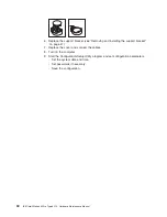


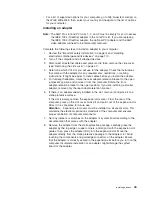


EMC shield
Filler panel
13
94
6. Touch the static-protective package containing the drive to any unpainted metal
surface on the computer; then, remove the drive from the package and place it
on a static-protective surface.
7. Set any jumpers or switches on the drive according to the documentation that
comes with the drive.
Note:
You might find it easier to install the new drive into the appropriate
opening on the front, and then attach the cables.
8. If you are installing a 5.25-in. drive in bay 2, push the drive into the bay; then,
use the two screws to attach the drive to the drive cage. If you are installing a
3.5-in. drive in bay 2, you must attach the 5.25-in. conversion kit, supplied with
your option, to the 3.5-in. drive.
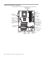
9. Determine whether the drive is an IDE or SCSI device; then, connect one end
of the appropriate signal cable into the back of the drive and the other end of
this cable into the appropriate IDE or SCSI connector on the system board.
See “Power and signal cables for internal drives” on page 50 for additional
information about cabling drives and “System-board internal connectors” on
page 38 for the location of IDE and SCSI connectors on the system board. If
there are open connectors on the cables connecting existing IDE or SCSI
drives, these cables can be used to connect the new drive.
10. Route the signal cable so that it does not block the airflow to the rear of the
drives or over the microprocessor.
11. Connect the power cable to the back of the drive. The connectors are keyed
and can be inserted only one way.
12. If you have other options to install or remove, do so now.
13. Replace the support bracket (see “Removing and installing the support
bracket” on page 41).
14. Replace the side cover (see “Replacing the side cover” on page 53).
15. Reconnect the external cables and power cords; then, turn on the attached
devices and the computer.
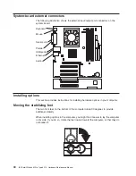
Installing a hard disk drive in bay 5, 6, or 7
Bays 5, 6, and 7 are in the drive cage. The drive cage is behind the front of the
adapter-support bracket.
48
IBM IntelliStation M Pro Type 6219: Hardware Maintenance Manual
Summary of Contents for 6219 - IntelliStation M - Pro
Page 1: ...IBM IntelliStation M Pro Type 6219 Hardware Maintenance Manual...
Page 2: ......
Page 3: ...IBM IntelliStation M Pro Type 6219 Hardware Maintenance Manual...
Page 6: ...iv IBM IntelliStation M Pro Type 6219 Hardware Maintenance Manual...
Page 10: ...viii IBM IntelliStation M Pro Type 6219 Hardware Maintenance Manual...
Page 26: ...16 IBM IntelliStation M Pro Type 6219 Hardware Maintenance Manual...
Page 70: ...60 IBM IntelliStation M Pro Type 6219 Hardware Maintenance Manual...
Page 88: ...78 IBM IntelliStation M Pro Type 6219 Hardware Maintenance Manual...
Page 110: ...100 IBM IntelliStation M Pro Type 6219 Hardware Maintenance Manual...
Page 127: ...Related service information 117...
Page 128: ...118 IBM IntelliStation M Pro Type 6219 Hardware Maintenance Manual...
Page 129: ...Related service information 119...
Page 130: ...120 IBM IntelliStation M Pro Type 6219 Hardware Maintenance Manual...
Page 131: ...Related service information 121...
Page 132: ...122 IBM IntelliStation M Pro Type 6219 Hardware Maintenance Manual...
Page 133: ...Related service information 123...
Page 143: ...Related service information 133...
Page 144: ...134 IBM IntelliStation M Pro Type 6219 Hardware Maintenance Manual...
Page 152: ...142 IBM IntelliStation M Pro Type 6219 Hardware Maintenance Manual...
Page 153: ......
Page 154: ...Part Number 71P9918 1P P N 71P9918...


