background image

Chapter 2 EC Gateway Unit


2.4  Part Names/Functions and External Dimensions


2-10 

ME0394-1A


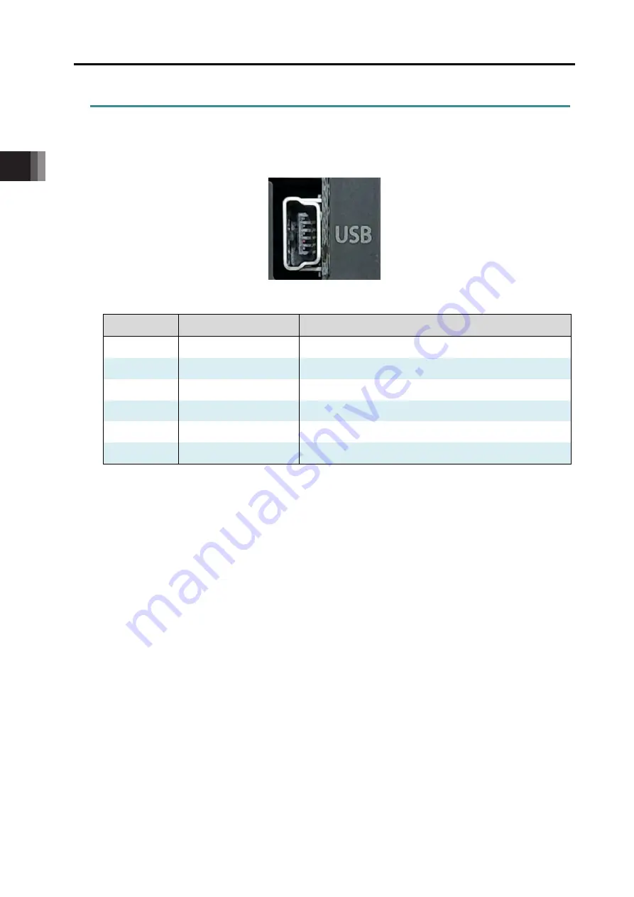
2.4.5 USB connector 


It is a connector to be connected to the PC software or gateway parameter configuration tool. 
For use, it is necessary to install the USB connection driver for RCON. 
For how to install the driver, refer to “PC software Instruction Manual (ME0155)”. 


Connector name: 51387-0530 (Molex) 


Pin No. 

Signal name 

Description 

VBUS 

USB power 

D- 

USB signal line - 

D+ 

USB signal line + 

NC 

Not connected 

GND 

0 V 

Shell 

GND 

0 V 


5


1


Summary of Contents for Rec

Page 1: ...ition ME0394 1A System Configuration and Specifications EC Gateway Unit EC Connection Unit Unit connection Installation and Wiring Operation Parameter Troubleshooting Chapter 1 Chapter 2 Chapter 3 Chapter 4 Chapter 5 Chapter 6 Chapter 7 ...

Page 2: ......

Page 3: ... place so that whoever is handling the product can refer to it quickly when necessary Important This instruction manual is an original document dedicated for this product This product cannot be used in ways not shown in this instruction manual IAI shall not be liable for any result whatsoever arising from the use of the product in any other way than what is noted in the manual The information cont...

Page 4: ...tion Manual this document ME0394 RCON System Instruction Manual ME0384 PC software RCM 101 MW RCM 101 USB Instruction Manual ME0155 Touch Panel Teaching Pendant TB 02 02D Instruction Manual ME0355 Touch Panel Teaching Pendant TB 03 Instruction Manual ME0376 24V Power Supply Unit PSA 24 Instruction Manual ME0379 Calculator Calculator Instruction Manual ME0381 ...

Page 5: ... this chapter explains the specifications and name of each part of the EC connection unit Chapter 4 Unit connection Installation and Wiring In this chapter explains how to link units install them and how to lay out wiring for REC System Chapter 5 Operation In this chapter explains about control signals how to operate and behaviours of ELECYLINDER Chapter 6 Parameter In this chapter explains how to...

Page 6: ... 11 1 5 5 Installation conditions 1 13 1 6 External dimensions 1 16 1 6 1 REC system 1 16 Chapter 2 EC Gateway Unit 2 1 Overview 2 1 2 2 How to Read the Model Number 2 2 2 2 1 How to read the model nameplate 2 3 2 3 EC Gateway Unit and Accessories 2 4 2 4 Part Names Functions and External Dimensions 2 5 2 4 1 Part names 2 5 2 4 2 LED display 2 7 2 4 3 AUTO MANU switch 2 8 2 4 4 SIO connector 2 9 2...

Page 7: ... Wiring between Actuator and EC Connection Unit 4 9 4 3 4 Example of Wiring for Field Network 4 10 4 3 5 Each field network wiring 4 12 4 3 6 Connection the teaching connector 4 18 4 3 7 Connection the USB connector 4 19 Chapter 5 Operation 5 1 Operation Function 5 1 5 2 Address Configuration 5 2 5 2 1 Overall address configuration example 5 3 5 2 2 Gateway status signals 5 6 5 2 3 ELECYLINDER Pos...

Page 8: ...7 2 EC Gateway Unit Alarm Causes and Countermeasures 7 2 7 2 1 Causes and countermeasures of individual alarms 7 2 7 3 Causes and countermeasures for ELECYLINDER alarms 7 5 7 3 1 Alarm Group 7 5 7 3 2 Troubleshooting for alarm groups 7 6 Revision history Post 1 ...

Page 9: ...ents essential for safety safety devices etc Do not use the product outside the range of the specifications Otherwise the product life may be drastically shortened and product damage or facilities stoppage may occur Do not use it in any of the following environments 1 Locations with flammable gases ignitable objects or explosives 2 Locations with potential exposure to radiation 3 Locations with am...

Page 10: ...is free of damage Do not climb on loads suspended from cranes Do not leave loads suspended from cranes for long periods Do not stand under loads suspended from cranes 3 Storage and Preservation For the storage and preservation environment see the installation environment However give especial consideration to the prevention of condensation Store the products so as to prevent them from falling over...

Page 11: ...ise this may lead to fire electric shock or abnormal operation of the product Never cut or reconnect the cables supplied with the product for the purpose of extending or shortening the cable length Otherwise this may lead to fire or abnormal operation of the product 3 Grounding Grounding must be performed in order to prevent electric shocks or electrostatic charge enhance noise resistant performan...

Page 12: ...Do not insert fingers or objects into the openings in the product Otherwise this may lead to injury electric shock product damage or fire When releasing the brake on a vertically oriented actuator be careful that it does not fall under its own weight catching the operator s hand or damaging workpieces 5 Teaching When working with two or more persons make it clear who is to be in charge and communi...

Page 13: ... the various setting switches while the equipment is live Otherwise this may lead to electric shock or abnormal operation 7 Automatic Operation Check before starting automatic operation or restarting after operation stop that there is nobody within the safety protection fence Before starting automatic operation make sure that all peripheral equipment is ready for automatic operation and that there...

Page 14: ... may lead to damage to the product When releasing the brake on a vertically oriented actuator be careful that it does not fall under its own weight catching the operator s hand or damaging workpieces The slider or rod may be misaligned from the stop position if the servo is turned OFF Avoid injury or damage due to unnecessary operation Be careful not to lose the cover or any removed screws and be ...

Page 15: ...roduct is not handled correctly will result in death or serious injury Danger Warning This indicates a potentially hazardous situation which if the product is not handled correctly could result in death or serious injury Warning Caution This indicates a potentially hazardous situation which if the product is not handled correctly may result in minor injury or property damage Caution Notice This in...

Page 16: ...or backup memory of this controller Registered position data and parameters are written in this memory and backed up Therefore these data will normally not be lost even if the power is turned off However be sure to save the latest data to enable a quick recovery process in case this controller needs to be replaced with a substitute due to breakdown etc How to save 1 Save to an external memory or a...

Page 17: ...e sure the safety factor of the timer setting is 2 to 4 times or more of the scan time As the timer is also processed within the scanning process setting below the scan time is dangerous The example shown in the diagram indicates that even if this controller performs output process once every 1 ms the PLC can only recognize once every 20 ms The PLC only performs the output process once every 20 ms...

Page 18: ...tioner mode etc The minimum set value of the 10 ms timer should be 2 and when required to set to 100 ms use the 10 ms timer and set it to 10 7 External communication ports The REC gateway unit has 2 types of communication port SIO port RS 485 round connector USB port USB mini B connector Do not connect multiple ports and perform communication simultaneously This may result in following errors Occu...

Page 19: ...nit is grounded at the positive terminal of the 24 VDC power supply a PC cannot be connected to the USB connector mini B of the EC gateway unit If connected directly short circuiting of the power will occur as shown in the diagram below causing malfunction of the PC USB A type 5 V DATA DATA GND FG EC Gateway unit Communication cable for PC software USB cable A mini B GND and FG shorting within PC ...

Page 20: ...nnecting a PC to the SIO connector of the gateway unit If a PC is connected to the gateway unit without using an SIO isolator the power will short circuit and cause the PC to malfunction Caution RS 232 conversion unit RCB CV MW cannot be used GND FG PC Conversion unit RCB CV USB 5 V SGA SGB GND FG 5V1 SGA SGA1 SGB SGB1 GND GND1 FG EC Gateway unit SIO isolator RCB ISL SIO 24 V 0 V Insulation Isolat...

Page 21: ... Compliance This product complies with the following overseas standards Refer to the Overseas Standard Compliance Manual ME0287 for more detailed information RoHS Directive CE Marking UL Certification To be Complied Soon To be Complied Soon Please contact IAI for more details ...

Page 22: ...breakdown or malfunction in question was caused by a specification defect malfunction or poor product quality Note that breakdowns due to any of the following reasons are excluded from the scope of warranty 1 Anything other than our product 2 Modification or repair performed by a party other than IAI unless approved by IAI 3 Anything that could not be easily predicted with the level of science and...

Page 23: ... high level of safety Accordingly as a rule our product cannot be used in these applications Contact IAI if you must use our product for any of these applications 1 Medical equipment used to maintain control or otherwise affect human life or physical health 2 Mechanisms and machinery designed for the purpose of moving or transporting people vehicles railway facilities aviation facilities etc 3 Mac...

Page 24: ...side Caution Homing direction cannot be changed with some models If it becomes necessary to reverse the homing direction after assembly to equipment check the model of the applicable actuator to ensure that the homing direction is changeable For models with which change is not possible the actuator must be replaced Contact IAI if anything is unclear The 0 in the figure below shows home The parenth...

Page 25: ...Actuator Coordinate System ME0394 1A Intro 17 4 Rotary type 330 degree rotation specification 0 330 ...

Page 26: ...guration 1 3 1 4 Configuration Unit List 1 4 1 5 Specifications 1 5 1 5 1 General specifications 1 5 1 5 2 Power supply capacity 1 7 1 5 3 Inrush current 1 10 1 5 4 Drive Cutoff Circuit 1 11 1 5 5 Installation conditions 1 13 1 6 External dimensions 1 16 1 6 1 REC system 1 16 R E C Chapter 1 ...

Page 27: ...tructed with combinations of EC units capable to connect four axes per each between the EC gateway unit that is an interface for the field network connection and the terminal unit terminal resistor EC unit is available for four units at the maximum 16 axes for connection There are seven types of the EC gateway units for CC Link for CC Link IE Field for DeviceNet for EtherCAT for EtherNet IP for PR...

Page 28: ... frame communication for a communication cycle time within 4 ms even with 16 axes connected A high heat dissipation structure is adopted to support ambient temperatures up to 55 C There is no need of a fan unit mounted 5 Enhanced preventive and predictive maintenance functions The present position and motor current value can be monitored as well as the travel count travel distance and motor overlo...

Page 29: ...ons 1 3 System Configuration ME0394 1A 1 3 1 3 System Configuration The following shows the system configuration Teaching tool Model TB 02 TB 03 Model RCM 101 MW RCM 101 USB Power supply unit Model PSA 24 Field network PLC Connectable actuators EC ...

Page 30: ...REC GW DV EtherCAT connection type REC GW EC EtherNet IP connection type REC GW EP PROFIBUS DP connection type REC GW PR PROFINET IO connection type REC GW PRT EC Connection Unit ELECYLINDER connection type RCON EC 4 Terminal Unit Enclosed to EC Gateway Unit RCON GW TRE REC configuration example When EC 16 axis is connected REC GW EC Connection Unit RCON EC Axes 0 to 3 RCON EC Terminal Unit 0V 24V...

Page 31: ... atmosphere Avoid corrosive gas and in particular avoid excessive dust Altitude 1 000m or less Vibration resistance Frequency 10 to 57 Hz Amplitude 0 075mm Frequency 57 to 150 Hz Acceleration 9 8m s2 XYZ directions Sweep time 10 minutes Number of sweeps 10 times Shock resistance Drop height 800mm 1 corner 3 edges 6 faces Overvoltage category I Electric shock protection mechanism Class III Pollutio...

Page 32: ...INET IO SIO interface Teaching port Communication method RS485 Communication speed 9 6 19 2 38 4 57 6 115 2 230 4 kbps USB port Communication method USB Communication speed 12Mbps PIO interface No Data recording device Position data and parameters to be stored in non volatile memory No limit to writing count Safety category compatibility Drive source cutoff method Drive cutoff by semiconductor Pow...

Page 33: ...of the motor power capacity and the peak current satisfies the maximum current of the motor power capacity However when multiple axes are connected provided that not all of the actuators operation timing is the same the resulting value is not a simple total because the rated current maximum current do not flow simultaneously The specifications related to the power capacity are as shown below Item ...

Page 34: ... EC Connection Unit 0 1A 4 0 4A OK Motor Power Supply When ELECYLINDER with power saving mode invalid 16 axes EC Connection Unit rated current 2 3 A 16 axes 91 2 A OK Note For those with no description of the rated current for the motor current amperage calculate with the maximum current Note Supposing that the operation pattern is that all axes only perform acceleration deceleration simultaneousl...

Page 35: ...ing current of the circuit breaker when select Rated Interrupting Current Short Circuit Current Primary Side Current Amperage Power Supply Voltage In Rush Current of IAI Power Supply Unit PSA 24 Item Conditions Specifications In Rush Current At Cold Start 25 C 100V AC 17A typ 200V AC 34A typ At Cold Start 40 C 100V AC 27 4A typ 200V AC 54 8A typ The pulse width that the in rush current flows in is...

Page 36: ... rush current would occur only on the EC connection unit The inrush current values are listed below Item Specifications Inrush current About 5 ms RCON EC Max 40 0A When multiple driver units are used depending on the capacity of the 24V DC power source a voltage drop might occur when the units are turned on ...

Page 37: ... an emergency stop switch on a teaching pendant There is an interface Drive Cutoff Connector MPI MPO on each axis available for external drive cutoff equipped on each EC connection unit The drive cutoff circuit by a semiconductor possesses a future for overcurrent detection and in rush current control Example of Wiring for Stop and Drive Cutoff Note 1 When there is nothing to be connected to the S...

Page 38: ...ce by pressing and holding the stop switch on a teaching pendant wired connection 2 To stop ELECYLINDER by cutting off the motor power source with an external circuit equipped with a contact such as a relay on a circuit line between MPI and MPO terminals on the drive cutoff connector Warning The teaching pendant can stop all the actuators connected to REC system however it cannot stop the system S...

Page 39: ...t is exposed to significant amounts of dust salt or iron powder Where the unit is subject to direct vibration or impact Where the unit receives direct sunlight Where the unit may come in contact with water oil or chemical spray Where vents are blocked see the section for installation and noise countermeasures If the unit is used in any of the following locations provide sufficient shielding measur...

Page 40: ...n top Ambient operating temperatur 0 to 55 C Installation method DIN rail mounting Installation conditions See figure below Ground Class D grounding Operating temperature range The operating temperature of the gateway unit EC Connection Unit is within the range of 0 to 55 C Caution Under conditions where the temperature is higher than 55 C the unit cannot be used regardless of the operating duty W...

Page 41: ...rces are shown below 1 AC solenoid valve magnetic switch relay Measure Install an anti noise device in parallel with the coil 2 DC solenoid valve magnetic switch relay Measure Install a diode in parallel with the coil or use the diode built in type Annealed copper wire 1 6 mm diameter Connect with a ground wire of 2 mm2 AWG14 Ground terminal Grounding resistance 100 Ω or less Class D grounding con...

Page 42: ...xternal dimensions W133 mm H115 mm D95 mm when four units of EC connection unit Mass About 675g when four units of EC connection unit External view See figure below Number of EC Connection Units 1 2 3 4 Max Connectable Number of Units 4 axes 8 axes 12 axes 16 axes A dimensions mm 65 2 87 8 110 4 133 0 Mass g 306 429 552 675 98 8 95 4 3 5 115 39 6 35 2 ...

Page 43: ...sories 2 4 2 4 Part Names Functions and External Dimensions 2 5 2 4 1 Part names 2 5 2 4 2 LED display 2 7 2 4 3 AUTO MANU switch 2 8 2 4 4 SIO connector 2 9 2 4 5 USB connector 2 10 2 4 6 24V power connector 2 11 2 4 7 Field network connector 2 12 2 4 8 Connectors 2 12 2 4 9 Terminal unit 2 13 2 4 10 External dimensions 2 14 R E C Chapter 2 ...

Page 44: ...2 5 Field Network General Specifications 2 16 2 5 1 CC Link 2 16 2 5 2 CC Link IE Field 2 17 2 5 3 DeviceNet 2 18 2 5 4 EtherCAT 2 19 2 5 5 EtherNet IP 2 20 2 5 6 PROFIBUS DP 2 21 2 5 7 PROFINET IO 2 22 ...

Page 45: ... host PLC It supports 7 kinds of field networks CC Link CC Link IE Field DeviceNet EtherCAT EtherNet IP PROFIBUS DP PROFINET IO By connecting the EC connection units RCON EC to REC System it is available to connect 16 axes at the maximum Teaching tool Model TB 02 TB 03 Model RCM 101 MW RCM 101 USB Power supply unit Model PSA 24 Field network PLC Connectable actuators EC EC Gateway unit ...

Page 46: ...d type CC CC Link connection specification CIE CC Link IE Field connection specification DV DeviceNet connection specification EC EtherCAT connection specification EP EtherNet IP connection specification PR PROFIBUS DP connection specification PRT PROFINET IO connection specification TRN Without terminal unit Terminal unit Single product model number RCON GW TRE Field network Connector I O type EC...

Page 47: ...2 3 2 2 1 How to read the model nameplate EC Gateway Unit Mark Explanation of Mark Use IAI specified cables only Terminal Unit Nameplate Location Model number Serial number Type Serial number Nameplate Location G G W W T T R R E E 0 0 1 1 2 2 3 3 4 4 5 5 6 6 7 7 8 8 9 9 ...

Page 48: ...kely case that any model number errors or missing parts come to light contact your local IAI distributor Part name Shape Quantity Remarks EC Gateway unit 1 Model example REC GW CC Terminal unit 1 Single product model number RCON GW TR Not supplied with TRN specification System I O connector 1 Single product model number DFMC1 5 5 ST 3 5 Phoenix Contact Field network connector 1 Depends on I O type...

Page 49: ...ernal Dimensions ME0394 1A 2 5 2 4 Part Names Functions and External Dimensions 2 4 1 Part names REC GW T P connector 24V power connector Front Top SYS LED T RUN LED AUTO MANU switch USB connector FIELDBUS STATUS 1 LED STATUS 0 LED C ERR LED MODE LED STOP LED ...

Page 50: ...Chapter 2 EC Gateway Unit 2 4 Part Names Functions and External Dimensions 2 6 ME0394 1A Left side Right side Connector Rear Connector bottom part DIN tab Connector upper part ...

Page 51: ...ation It also lights up green when an alarm is generated in the driver unit or simple absolute unit Orange Light ON Gateway alarm triggered STOP Red Light ON STOP signal input OFF driver unit drive power cut off Light OFF STOP signal input ON MODE Green Light ON AUTO automatic operation mode ON Light OFF MANU manual operation mode ON C ERR Orange Light ON Field network error generated Light OFF Fi...

Page 52: ... of commands from host devices such as PLCs MANU Teaching operation mode that enables reception of commands from host devices such as PLCs Caution Switching from MANU to AUTO while an operation command being input from the PLC should allow the command signal accepted and make operation Turn an operation command off when set to MANU or stopping a program so it would not start operating at the timin...

Page 53: ...oftware PC software can also be connected with a USB Pin No Signal name Description 1 TP_SD Teaching pendant PC RS 485 differential signal side 2 TP_SD Teaching pendant PC RS 485 differential signal side 3 T5V Teaching pendant 5 V output 4 ENB Enable signal input 5 STOPA Stop line A 6 T24V Teaching pendant 24 V output 7 GND 0 V 8 STOPB Stop line B 9 shell GND 0 V ...

Page 54: ...tware or gateway parameter configuration tool For use it is necessary to install the USB connection driver for RCON For how to install the driver refer to PC software Instruction Manual ME0155 Connector name 51387 0530 Molex Pin No Signal name Description 1 VBUS USB power 2 D USB signal line 3 D USB signal line 4 NC Not connected 5 GND 0 V Shell GND 0 V 5 1 ...

Page 55: ...d to the EC gateway unit Pin No Signal name Description 1 GND 0 V 2 MP Motor power 24 V input Motor power connector compatible wire Item Specifications Compatible wire AWG20 to 8 Copper Wire Strip length 15 0mm Rated Temperature on Isolation Coating 60 C or more Caution Select a wire with thickness that tolerates the rated current total value obtained in 1 5 3 Specifications Power supply capacity ...

Page 56: ...d networks Field network details are listed in 2 5 Field Network General Specifications 2 4 8 Connectors A connector for use between units Two identical connectors are used The connectors have a floating structure that absorbs connector misalignment due to housing mating or mounting misalignment between connectors Receptacle connector Plug side connector ...

Page 57: ...Chapter 2 EC Gateway Unit 2 4 Part Names Functions and External Dimensions ME0394 1A 2 13 2 4 9 Terminal unit RCON GW TRE Left side Right side Rear Connector Terminal Unit Card ...

Page 58: ...es Functions and External Dimensions 2 14 ME0394 1A 2 4 10 External dimensions EC Gateway unit Item Specifications External dimensions W 30 mm H 115 mm D 95 mm Mass About 135g External view See figure below 115 39 6 35 2 95 98 8 30 4 7 3 5 ...

Page 59: ...eway Unit 2 4 Part Names Functions and External Dimensions ME0394 1A 2 15 Terminal unit Item Specifications External dimensions W 12 6 mm H 115 mm D 95 mm Mass About 48g External view See figure below 115 12 6 95 98 8 ...

Page 60: ... s 1 pin FG are connected internally LED display Name Panel notation Display color Status Description STATUS 0 RUN Green Light ON After joining the network refresh poll normal reception or refresh normal reception Light OFF 1 Network not joined 2 Channel carrier detected 3 Timeout 4 Hardware reset in progress STATUS 1 ERR Orange Light ON 1 CRC error 2 Station number setting error when reset cancel...

Page 61: ...Status Description STATUS 0 MS Green Light ON Normal operation Light OFF Hardware error generated Orange Light ON Error generated Light OFF Normal operation STATUS 1 NS Green Light ON Cyclic transmission ON Blinking Cyclic transmission OFF Light OFF Cyclic transmission not yet implemented fragmented Orange Light ON Receive data error Light OFF Receive data normal LINK Green Light ON Link up Light ...

Page 62: ... Panel notation Display color Status Description STATUS 0 MS Green Light ON Normal operation Blinking 1 Hz No configuration information incomplete information or device test operation required Orange Light ON Non recoverable fault Blinking 1 Hz Recoverable fault Green orange Alternate blinking Self diagnosis STATUS 1 NS Green Light ON Online connection established Blinking 1 Hz Online connection n...

Page 63: ...Status Description STATUS 0 ERR Orange Light ON Signal component module error Blinking continuous Configuration information settings error ON 200 ms OFF 200 ms Blinking 2 times Watchdog timer timeout ON 200 ms x 2 OFF 1 000 ms Light OFF Initialized status STATUS 1 RUN Green Light ON Normal operation OPERATION status Blinking continuous PRE OPERATION status ON 200 ms OFF 200 ms Blinking 1 time SAFE...

Page 64: ...display Name Panel notation Display color Status Description STATUS 0 MS Green Light ON Normal operation Blinking No configuration information or scanner in idle status Orange Light ON Non recoverable fault Blinking Recoverable fault STATUS 1 NS Green Light ON Online connection established Blinking Online connection not established Orange Light ON Fatal error IP address duplication error Blinking ...

Page 65: ...ot connected 8 A Line Signal line A RS 485 9 NC Not connected Housing FG Frame ground control power connector 1 pin FG connected internally LED display Name Panel notation Display color Status Description STATUS 0 MS Green Light ON Initialization complete Blinking Initialization complete diagnosis event found Orange Light ON Exception error Green orange Light OFF Uninitialized STATUS 1 NS Green Li...

Page 66: ...Light ON Normal communication Blinking 1 time Network being diagnosed Blinking 2 times Engineering tool is identifying the node Orange Light ON Exception error generated hardware failure Blinking 1 time Settings and actual network configuration differ Blinking 2 times IP address not set Blinking 3 times Station name not set Blinking 4 times Internal error generated Green orange Light OFF Initializ...

Page 67: ...3 3 Components 3 4 3 4 Part Names Functions and External Dimensions 3 5 3 4 1 Part names 3 5 3 4 2 LED display 3 7 3 4 3 Jog switch 3 8 3 4 4 Brake release switch 3 9 3 4 5 Connectors for EC Connection 3 10 3 4 6 Drive source shutoff connector 3 11 3 4 7 Connectors 3 12 3 4 8 External dimensions 3 13 R E C Chapter 3 ...

Page 68: ...nnection unit ELECYLINDER can be controlled in the field network communication Also the maximum number of ELECYLINDER available to be connected to one unit of the EC connection unit should be four axes In this chapter explains the EC connection unit RCON EC Teaching tool Model TB 02 TB 03 Model RCM 101 MW RCM 101 USB Power supply unit Model PSA 24 Field network PLC Connectable actuators EC EC Conn...

Page 69: ...umber ELECYLINDER capable to be connected to the EC connection unit is the option ACR only E C ACR EC Connection Unit model RCON Type Number of Axes EC ELECYLINDER 4 Four axis type EC Connection Unit Model RCON EC 4 Series Type Lead Motor Joint Type Stroke Option ACR RCON EC connection type Cable Length ...

Page 70: ... How to Read the Model Number 3 3 ME0394 1A 3 2 1 How to read the model nameplate EC Connection Unit Mark Explanation of Mark Use IAI specified cables only Nameplate Location Serial number Caution Mark Type Model number Serial number ...

Page 71: ...he details of the enclosed components In the unlikely case that any model number errors or missing parts come to light contact your local IAI distributor EC Connection Unit Part name Shape Quantity Remarks EC Connection Unit 1 Model example RCON EC Drive source shutoff connector 1 Model DFMC1 5 4 ST 3 5 Supplied with EC Connection Unit First Step Guide 1 ME0395 Safety Guide 1 M0194 ...

Page 72: ...E0394 1A 3 4 Part Names Functions and External Dimensions EC Connection Unit 3 4 1 Part names RCON EC Front T RUN LED Forward end LED 1st to 4th Axes Backward end LED 1st to 4th Axes SYS LED Brake Release Switch 1st to 4th Axes Jog switch 1st to 4th Axes Drive source shutoff connector ...

Page 73: ...Chapter 3 EC Connection Unit 3 4 Part Names Functions and External Dimensions ME0394 1A 3 6 Left side Right side Rear Connector bottom part Connector upper part Connector Connector DIN tab ...

Page 74: ...ation communication failed Orange Light ON Bus communication error generated SYS Green Light ON Servo ON Blinking Servo OFF Red Light ON Alarm triggered STOP signal input OFF Drive source cutoff triggered LS1 ALM I 1st axes II 2nd axes III 3rd axes IV 4th axes Green Light ON Movement to Forward End Complete Blinking Stop Red Light ON Alarm triggered LS0 I 1st axes II 2nd axes III 3rd axes IV 4th a...

Page 75: ...ncel the home return operation The operation on on the jog switch is valid only in MANU Mode It should be invalid in AUTO Mode Also when a window to operate actuators is open on a teaching tool the jog switch should be inactivated If a window capable to operate actuators gets opened during operation with the jog switch an actuator should decelerate and stop Setting RCON EC Jog Switch in GW Paramet...

Page 76: ...forced release regardless of servo ON OFF except when control power is OFF Symbol Description RLS Brake release Brake Release NOM Brake lock Normal Warning Be careful when releasing the brake Releasing carelessly may cause injury or damage to the actuator body workpiece or surrounding devices due to the slider or rod falling After releasing the brake be sure to return the brake to the enabled stat...

Page 77: ...ld be assigned to the EC connection unit even if ELECYLINDER is not connected to all of four An axis number that an axis is not connected should not be pulled one number forward RCON EC Pin No Signal name Description 1 24V MP Motor power 24V 2 GND 0V 3 IN0 Input 0 4 IN1 Input 1 5 IN2 Input 2 6 SD Communication Line 7 OUT0 Output 0 8 OUT1 Output 1 9 OUT2 Output 2 10 SD Communication Line 11 BKRLS B...

Page 78: ...escription 1 MPO_3 Motor power output 4th axes 2 MPO_2 Motor power output 3rd axes 3 MPO_1 Motor power output 2nd axes 4 MPO_0 Motor power output 1st axes 5 MPI_3 Motor power input 4th axes 6 MPI_2 Motor power input 3rd axes 7 MPI_1 Motor power input 2nd axes 8 MPI_0 Motor power input 1st axes Cable side connector compatible wire Item Specifications Compatible wire AWG20 to 16 Copper Wire Strip le...

Page 79: ...0394 1A 3 12 3 4 7 Connectors A connector for use between units Two identical connectors are used The connectors have a floating structure that absorbs connector misalignment due to housing mating or mounting misalignment between connectors Plug side connector Receptacle connector ...

Page 80: ... Functions and External Dimensions 3 13 ME0394 1A 3 4 8 External dimensions EC Connection Unit Item Specifications External dimensions W 22 6 mm H 115 mm D 95 mm Mass About 123g External view See figure below 1 22 6 7 98 8 95 4 3 5 115 39 6 35 2 ...

Page 81: ...2 3 Unit mounting 4 5 4 3 Wiring method 4 6 4 3 1 Power supply wiring to REC system 4 6 4 3 2 REC System Connection Cable 4 8 4 3 3 Wiring between Actuator and EC Connection Unit 4 9 4 3 4 Example of Wiring for Field Network 4 10 4 3 5 Each field network wiring 4 12 4 3 6 Connection the teaching connector 4 18 4 3 7 Connection the USB connector 4 19 R E C Chapter 4 ...

Page 82: ... later Teaching pendant TB 02 TB 02D Ver 2 70 or later TB 03 Ver 2 70 or later Gateway parameter configuration tool Ver 3 1 7 0 or later The gateway parameter configuration tool is included in the PC software but you can also download the latest version from our website For the operation of PC software and teaching pendant refer to the following instruction manual Reference PC software operating m...

Page 83: ...ample of using and details the gateway parameter configuration tool refer to 5 4 How to Use the Gateway Parameter Configuration Tool page 5 24 Also Quick Start Guide explaining how to set up each network is available to download from IAI homepage Quick Start Guide available in Japanese only ...

Page 84: ... on the far left of the REC system Terminal unit Placed on the far right of the REC system 2 Number of Connectable Units of EC Connection Unit Up to 16 axes can be controlled with each EC gateway unit Even though the EC connection units have a structure capable to be connected with no upper limit have them connected up to four units 16 axes at the maximum EC connection unit occupies the domains an...

Page 85: ...anel and position on the panel end 2 The 2 sections circled with a dashed line and the 4 positioning bosses within the square dotted lines are used as a total of 6 mating sections for positioning 2 units 3 When positioning is completed insert the cable connectors 2 so that they are firmly connected 4 Turn the operating parts of the connector upper bottom part towards the rear rotating firmly until...

Page 86: ...4 1A 4 2 3 Unit mounting REC System is available only with DIN rail installation Pull down the DIN tab visible from the lower part of the housing rear red color part in a dashed line in the figure below mount on the DIN rail then push the DIN operating part upward to lock it Front Rear DIN tab ...

Page 87: ... the EC gateway unit to IAI 24V DC power supply unit Have a wiring work following the layout below Wiring method to power connector 1 Refer to the table below for the wire diameter for each cable 2 The stripped length on a cable should be 15mm 3 Insert the wire all the way into the terminal port while pushing the flathead screwdriver into the hole next to the wire insertion port 4 Remove the screw...

Page 88: ...2 Copper wire FG AWG14 to 12 Copper wire Use cables with their rated temperature on the isolation sheath at 60 C or higher The controller current consumption varies depending on the controller model and the motor type of the actuator to be connected Refer to 1 5 3 Power supply capacity Caution Use wires with diameter large enough for allowable current higher than the current actually used Smaller ...

Page 89: ...ER side EC Connection Unit side 4 way Connector Cable Code CB REC2 PWBIO RB The cable lengths should be 1m at shortest and 10m at longest Order can be made in every 1m of length Shown below is an example for the model types Cable Length 1m CB REC 2 PWBIO010 RB Cable Length 3m CB REC 2 PWBIO030 RB Cable Length 10m CB REC 2 PWBIO100 RB Free Choice of Eject Direction from 4 Ways Ejection to Top Eject...

Page 90: ...nnection below to insert the connectors to ELECYLINDER and the EC connection unit Push the connectors inward till it makes click sound The axis number should be determined by the position of the connector on the EC connection unit Insert until it clicks REC System EC Connection Unit Insert until it clicks ELECYLINDER ELECYLINDER Connection Cable CB REC PWBIO RB ...

Page 91: ...C manufactured by Mitsubishi Electric as the host PLC Connecting the host PLC and two systems REC System CC Link dedicated cable prepared by the customer The terminal resistor of the CC Link master unit is to be prepared by the customer Host PLC prepared by the customer CC Link master unit prepared by the customer Terminal resistor supplied with EC Connection Unit ELECYLINDER ELECYLINDER REC Syste...

Page 92: ...te 1 between the connectors DA and DB at the network terminal end only The terminal resistor of the CC Link master unit is to be prepared by the customer 5 Other CC Link dedicated cables are wired in the same manner as in 1 to 4 Point The terminal resistor to be used may differ depending on the CC Link dedicated cable type Cable FANC SBH CC Link dedicated high performance cable Terminal resistor 1...

Page 93: ... DA blue Signal line A CC Link dedicated cable 2 DB white Signal line B 3 DG yellow Digital ground 4 SLD Connects the shield of shielded cables 5 pin FG and control power connector 1 pin FG connected internally 5 FG Frame ground 4 pin SLD and control power connector 1 pin FG connected internally Controller side Connector top view Shield SLD Yellow DG White DB Blue DA REC CC Link Specification Mast...

Page 94: ...lded 8P8C modular jack RJ 45 Pin No Signal name Description Compatible wire diameter 1 TD Transmit data For the Ethernet cable use a straight STP cable of Category 5e or higher 2 TD Transmit data 3 RD Receive data 4 Not used 5 Not used 6 RD Receive data 7 Not used 8 Not used Controller side Connector top view L ER LINK L ER LINK Ethernet straight cable Category 5e or higher Aluminum tape and braid...

Page 95: ...lack Power supply cable side DeviceNet dedicated cable 2 CAN L blue Signal data Low side 3 Digital ground 4 CAN H white Signal data High side 5 V red Power supply cable side Controller side Connector top view Shield Blue CAN L Black V White CAN H Red V Master unit Slave device The communication power must be supplied from the outside Grounding resistance 100 Ω or less Class D grounding constructio...

Page 96: ... 5 or higher shielded 8P8C modular jack RJ45 Pin No Signal name Description Compatible wire diameter 1 TD Transmit data For the Ethernet cable use a straight STP cable of Category 5 or higher 2 TD Transmit data 3 RD Receive data 4 Not used 5 Not used 6 RD Receive data 7 Not used 8 Not used Controller side Connector top view 1 8 1 8 OUT IN Ethernet straight cable Category 5 or higher Aluminum tape ...

Page 97: ...ry 5 or higher shielded 8P8C modular jack RJ45 Pin No Signal name Description Compatible wire diameter 1 TD Transmit data For the Ethernet cable use a straight STP cable of Category 5 or higher 2 TD Transmit data 3 RD Receive data 4 Not used 5 Not used 6 RD Receive data 7 Not used 8 Not used Controller side Connector top view 1 8 Ethernet straight cable Category 5 or higher Aluminum tape and braid...

Page 98: ...tion Compatible wire diameter 1 NC Not connected PROFIBUS DP dedicated cable Type A EN5017 2 NC Not connected 3 B Line Signal line B RS 485 4 RTS Transmission request 5 GND Signal GND insulation 6 5 V 5 V output isolated 7 NC Not connected 8 A Line Signal line A RS 485 9 NC Not connected Controller side Connector top view 5 1 9 6 Red B line positive side Green A line negative side Shield Cable Mas...

Page 99: ...by Hosiden Corporation Cable side mini DIN 8 pin Refer to 2 4 4 SIO Connector for the pin assignment Caution Set Operation Mode Setting Switch to MANU side when a teaching tool is connected Turn the power OFF before disconnecting a teaching tool USB connector and teaching connector cannot be used at the same time Teaching connector is prioritized Teaching pendant PC PC connection cable Supplied wi...

Page 100: ...or specification Connector to be Used USB mini B 51387 0530 Molex Connector name USB Communication Specification Conformed to USB 2 0 480M High Speed 12Mbps Full Speed Maximum connection distance 5m Connected unit PC USB port Connection cable USB cable Controller side mini B Refer to 2 4 5 USB connector for the pin assignment PC USB cable A mini B prepared by the customer U US SB B 5 1 USB connect...

Page 101: ...5 3 I O Signals 5 14 5 3 1 Input and Output Signal Features in EC Connection Unit 5 14 5 3 2 Caution for REC System 5 17 5 3 3 Timing of basic operation 5 18 5 3 4 Basic Operations of ELECYLINDER 5 19 5 4 Gateway Parameter Configuration Tool 5 24 5 4 1 Tool startup 5 24 5 4 2 Menu descriptions 5 25 5 4 3 Explanation of Features in Special Parameter Setting 5 27 5 4 4 Explanations of Monitoring Men...

Page 102: ...h unit of ELECYLINDER 3 ELECYLINDER units start moving 4 A position detection signal gets output from ELECYLINDER Forward end or backward end 5 The position detection signal gets output from REC EC connection unit to PLC ELECYLINDER continues its operation while a movement command signal ST0 ST1 is on and a position detection signal LS0 LS1 turns on after the operation is complete If the movement ...

Page 103: ...unit It is not available to select an operation mode in the EC connection unit 1 Fixed region configuration PLC output REC REC PLC input High byte Low byte Word count High byte Low byte Word count Gateway control region Reserved 1 Gateway status signal 1 2 EC connection unit data region configuration per unit High byte Low byte Word count High byte Low byte Word count Control signal region Control...

Page 104: ...signal Unit 3 RWr 03H Status signal Unit 3 1 Regardless of the number of option units the occupied size should be Ver 1 10 extension cyclic multiplied by one and number of occupied stations one 2 The EC connection unit occupies domains and axis numbers for four axes one word even though not all of four axes are connected For CC Link IE Field Fixed 1 word region is assigned to the bit register RX R...

Page 105: ...ignal Unit 1 Status signal Unit 1 6 to 7 Control signal Unit 2 Status signal Unit 2 8 to 9 Control signal Unit 3 Status signal Unit 3 Relative byte is the byte address relative to the gateway head 1 The EC connection unit occupies domains and axis numbers for four axes one word even though not all of four axes are connected For EtherCAT The occupied size for EtherCAT should be fixed at 32 bytes re...

Page 106: ...ignal Gateway status signal Control signal Unit 0 Status signal Unit 0 Control signal Unit 1 Status signal Unit 1 Control signal Unit 2 Status signal Unit 2 2 Control signal Unit 3 Status signal Unit 3 Reserved Reserved Reserved Reserved Reserved Reserved 1 The EC connection unit occupies domains and axis numbers for four axes one word even though not all of four axes are connected ...

Page 107: ...byte Relative module Gateway Status signal b15 b14 b13 b12 b11 b10 b9 b8 RX 0 0 0 0 ALMH MOD ESTP b7 b6 b5 b4 b3 b2 b1 b0 1 ALMC128 ALMC64 ALMC32 ALMC16 ALMC8 ALMC4 ALMC2 ALMC1 Address is the address relative to the gateway head CC Link CC Link IE Field and DeviceNet have word addresses while PROFIBUS DP EtherNet IP and EtherCAT use byte addresses PROFINET IO uses 4 word module addresses The in CC...

Page 108: ...aken parameter setting Confirm as needed b14 Not available b13 MOD Turns ON if MANU is selected with the unit front operation mode setting switch and turns OFF when AUTO is selected b12 ESTP It turns on with the STOP input from a teaching pendant Once it turns on all the connected axes get into stop status b11 b8 Not available b7 ALMC 1 to 128 Outputs alarm codes caused by the gateway For details ...

Page 109: ...dant operating method PC software RCM 101 manual ME0155 Touch Panel Teaching Pendant manual TB 02 02D ME0355 TB 03 ME0376 Here shows an example of a screen in the teaching pendant TB 02 03 about the position table The items to be set should be the same in the PC software Simple Data Setting Window Caution Make sure to touch the Transfer key after setting or adjusting the data Switching the screen ...

Page 110: ...en the velocity is set to a value lower than the pressing speed the pressing operation should be performed in the set velocity The pressing speed should differ depending on the models Refer to an instruction manual of each ELECYLINDER or a catalog for detail Touch Switch Unit and the unit switches to mm s and can be registered in 0 01mm s unit Deceleration or G Deceleration at the stop of operatio...

Page 111: ...ing Force or N Displayed only in pressing operation It is the current limit value at the pressing operation Set in a value from 20 to 70 Note Touch Switch Unit and input in N unit is also available Note The input range available for the pressing current limit value should differ depending on the models Refer to an instruction manual of each ELECYLINDER for detail Caution The pressing force display...

Page 112: ...CC Link IE Field and DeviceNet have word addresses PROFIBUS DP EtherNet IP and EtherCAT use byte addresses and PROFINET IO uses 4 word module addresses b15 b14b13b12b11b10 b9 b8 b7 b6 b5 b4 b3 b2 b1 b0 E3RD ALM LS1 PE1 LS0 PE0 E2RD ALM LS1 PE1 LS0 PE0 E1RD ALM LS1 PE1 LS0 PE0 E0RD ALM LS1 PE1 LS0 PE0 Status signal 4th Axis Status signal 3th Axis Status signal 2nd Axis Status signal 1st Axis b15 b1...

Page 113: ... stop on the way with off Page 5 14 b8 ST0 Drive Backward Drives backward with on drives backward after home return operation when home return not complete decelerate and stop on the way with off Page 5 14 Control signal 2nd Axis b7 Not available b6 RES Alarm Cancel Alarm cancelled with on Page 5 15 b5 ST1 Drive Forward Drives forward with on drives forward after home return operation when home re...

Page 114: ... 5 15 to 16 b8 LS0 PE0 Driving Backward Complete Pressing Complete It turns on when an actuator gets in the detection range of the backward end It turns on when pressing operation completes Page 5 15 to 16 Status signal 2nd Axis b7 E1RD Operation Ready On Operation ready servo on Page 5 16 b6 ALM Alarm break contact ON No alarm OFF Alarm generated Page 5 16 b5 LS1 PE1 Driving Forward Complete Pres...

Page 115: ...egins Turning the ST signal OFF midway through home return operation will cause a gradual stop Home return status complete When the ST signal is turned ON the ELECYLINDER moves Backward and Forward While the ST signal is ON operation will continue until the Backward end or Forward end is reached Turning the ST signal OFF midway through operation will cause a gradual stop Caution If stopped when th...

Page 116: ...omplete signals The LS signals turn ON when the current ELECYLINDER position is within the detection range configured at the backward and forward ends They turn ON when within the detection range regardless of whether the servo is ON or OFF The backward end and forward end set values relationship to LS0 and LS1 signals ON is as follows In this example the LS signal detection range is 0 10mm To adj...

Page 117: ...rm occurs Always monitor the ALM signal using the master device If it turns OFF immediately take appropriate safety countermeasures with the equipment as a whole 6 Operation ready E RD PLC input signal It turns on when the operation is ready servo on when communication established in normal condition between RCON EC and EC It shows 0 1st axis on EC connection unit ready for operation 1 2nd axis on...

Page 118: ...n ELECYLINDER equipped with a Digital Speed Controller is connected to the EC connection unit 1 the screen would not be able to move to the trial run window for the Digital Speed Controller if the mode switch on the EC gateway unit is set AUTO 2 the trial run window on the Digital Speed Controller should close if the mode switch on the EC gateway unit is set MANU AUTO while the trial run window is...

Page 119: ...ervo on ELECYLINDER automatically turns on For details on the gateway status signal refer to 5 2 Address Configuration Gateway control status signal page 5 6 20ms TYP Home return Mechanical end Drive source cutoff cancel Drive source cutoff status Safety circuit status 24V power Input 24V DC Home return signal HOME STO ST1 Input Home return complete HEND LS0 LS1 Output EC Connection Unit Backward ...

Page 120: ...1 When the ST0 signal is turned ON backward motion begins towards the mechanical end The movement speed is 20mm s 2 Once the mechanical end is struck the direction will be reversed and forward motion will begin The unit will move forward until the home position then stop 3 After that it will continuously move forward until the backward end where it stops as operation is complete Caution In the hom...

Page 121: ... Input ST1 t2 Moves to the forward end 6 Output LS1 EC Connection Unit Forward End LED On Moved to the forward end 7 Input ST0 t2 Moves to the backward end 8 Output LS0 Moved to the backward end 9 After this 5 to 8 repeat t1 Wait approximately 0 5 seconds from when the E RD signal turns ON before inputting the first command t2 The time taken for the ELECYLINDER actually to reach the forward or bac...

Page 122: ...radual stop causes the ELECYLINDER to begin operation again Within the detection range the LS signal turns ON even if the ELECYLINDER is mid operation Make sure that ST0 and ST1 do not turn ON simultaneously This may result in unpredictable operation Pressing operation Establish the setting for the operating conditions and position setting in the simple data setting window before performing the pr...

Page 123: ...R or a catalog for detail The workpiece remains pressed after the pressing is completed If the workpiece moves or pushes back it may be pressed even further Hitting a workpiece during the approaching operation will cause Alarm Group A Overload Alarm ST signal PE signal ELECYLINDER movement PE signal ON ST signal OFF Pressing operation Approach operation Not ON at failure to contact Pressing comple...

Page 124: ...ward end is complete Consider a master device sequence or detection method based on the content below If no contact is made the PE signal will not turn ON A timer is required to determine if no contact has been made After a non contact operation the unit will stop in the pressing operation status If the workpiece shifts once pressing complete is determined and the PE signal is ON the ELECYLINDER w...

Page 125: ...e displayed Even if the gateway unit cannot be detected the main screen will be displayed When you press Import on this screen parameters will be imported from the detected gateway unit Press the Transfer button to transfer the parameters However note that they cannot be transferred if the address or communication speed is not selected Main screen initial state Main screen After Parameters Read in...

Page 126: ...aved parameter file and reflects it to the main screen Save Saves the parameters held by the tool to a file Exit Terminates the tool Settings menu Click the Setting menu in the upper left of the main screen to display the settings menu items Specialty Parameter Sets parameters related to gateway unit processing Refer to 5 4 3 Explanation of Features in Special Parameter Setting Port Config Sets th...

Page 127: ...nitor cannot be selected before reading in the parameters I O data Displays the communication contents between the host PLC and gateway unit See I O Data register monitor on page 5 30 Diagnostic Information Option unit information should be displayed See Diagnostic information on page 5 31 AlarmList L Imports and displays the alarm list held in the gateway unit See Alarm list on page 5 31 ...

Page 128: ... this is used to set the number of communication retries with the connected axis GW parameters 3 Delay time of driver reclosing Latency interval when supplying power to each unit of the EC connection unit one by one should be set It is used for the purpose of reducing inrush current by shifting the timing of power supplied to each axis The initial value for the latency is 5ms for each unit ...

Page 129: ...le this parameter is activated the enable signal gets valid Byte swap Set the byte swap See Byte swap on page 5 29 Option Unit Parameter RCON EC JOG Switch Select whether to activate inactivate the jog switch on the EC connection unit The setting to activate inactivate should be reflected to all the units of the EC connection unit that are connected to the gateway unit ...

Page 130: ...n Tool 5 29 ME0394 1A Byte swap Swaps the master and slave bytes of transmitted received data Set according to the master to be connected as necessary ON OFF Input register data data Output register data data ON OFF PLC RWwnn ON OFF PLC RWrnn ON OFF ON OFF ...

Page 131: ...rom the master and transmission data returned to the master are displayed on this register monitor screen Data read cycle Select the update cycle of the display data between 100 and 500 ms Display switch Select either binary or hexadecimal display SYNC Scroll When checked the transmitted received data will be scrolled at the same time Data reading cycle Display switch Synchronous scroll ...

Page 132: ...tion error occurrence in the EC connection units should be displayed Alarm list Press Refresh to read out the alarm list again from the gateway unit Press Clear to delete all alarm lists held by the gateway unit Press Save to save the alarm list held by the gateway unit in CSV format For the alarm details refer to Chapter 7 Troubleshooting ...

Page 133: ...Parameter 6 1 Parameter list 6 1 6 2 Parameter Details 6 2 R E C Chapter 6 ...

Page 134: ... 4 4 Home position adjustment mm 0 to 9 999 99 According to ELECYLINDER specifications 6 5 5 Smooth accel decel setting Disabled enabled Disabled 6 6 6 Current control setting at stop Disabled Powerful stop Enabled Energy saving stop Disabled 6 7 7 Wireless function setting Disabled enabled Enabled 6 8 8 Power saving setting Disabled enabled Disabled 6 8 Caution No 1 3 4 default factory settings d...

Page 135: ...t is 0 01mm Set to your desired stroke length The controller automatically adds 0 30mm and controls monitors the operation range Set the operating stroke between 0 and 80mm by changing Parameter No 1 to 80 00mm Caution Set within the ELECYLINDER movable range Setting to a value that exceeds the maximum stroke will result in collision with the forward side mechanical stopper This may damage the ELE...

Page 136: ...end forward end When the ELECYLINDER enters the detection range the backward complete or forward complete signal turns ON The minimum setting unit is 0 01mm The LS signal detection range for the conditions below is shown in the figure Backward end 0 00mm Forward end 100 00mm Parameter No 2 0 10mm Caution A value smaller than the minimum resolution cannot be set Minimum resolution mm p ball screw l...

Page 137: ...d For standard specification the motor side is home If Parameter No 3 is Forward If Parameter No 3 is Reverse Caution Changing the home return direction reverses the operation direction After changing this parameter always perform home return reset absolute reset Even if the operation direction is reversed check that the moving parts do not interfere with any other objects If the moving parts coll...

Page 138: ...tion upon reversing the default home return direction after purchase 3 To eliminate a slight deviation from the previous home position generated after replacing the ELECYLINDER If Parameter No 4 is 0 30mm the relationship between mechanical stopper and home position is as follows Caution If adjusting Parameter No 4 simultaneously adjust Parameter No 1 Operation range adjustment with parameter No 1...

Page 139: ...he shocks of acceleration deceleration without delaying the operation time If Disabled the above functionality is not enabled Setting Acceleration deceleration pattern Operation waveform image Disabled Trapezoid Enabled S motion Caution For operation in which the acceleration time or deceleration time exceeds 2 seconds do not Enable smooth accel decel settings Normal operation will not be possible...

Page 140: ...e unit to a complete stop If Enabled a current appropriate to the load will be transmitted to the motor stopping it This limits the amount of power consumed while stopping If abnormal noise or vibration occurs during a gradual stop setting to Enabled may fix the issue Moreover setting to Enabled can also fix issues in which the command position cannot quite be attained Caution If Disabled even if ...

Page 141: ...ion model number Power saving setting Parameter No 8 No Name Unit Input range Default initial value setting 8 Power saving setting Disabled Enabled Disabled Either Enabled or Disabled can be selected for the ELECYLINDER power saving setting When Enabled the power capacity can be reduced up to 40 compared to Disabled mode but the maximum speed maximum acceleration deceleration and payload decrease ...

Page 142: ...Gateway Unit Alarm Causes and Countermeasures 7 2 7 2 1 Causes and countermeasures of individual alarms 7 2 7 3 Causes and countermeasures for ELECYLINDER alarms 7 5 7 3 1 Alarm Group 7 5 7 3 2 Troubleshooting for alarm groups 7 7 R E C Chapter 7 ...

Page 143: ...connection error disconnection or snagging Cut off the main power supply of the equipment to avoid electric shock and remove the cables around the measurement point to avoid conductivity through the surrounding circuit before checking the conductivity 7 Check the network terminal resistor mounting status and resistance 8 Check the I O signals Use a teaching pendant to check for inconsistency or ab...

Page 144: ...actuator axes Countermeasure Reboot the power If it occurs again contact IAI 62 862 Dependent axis internal communication error reception Cause RCON internal communication error Communication failure with driver unit connecting actuator axes Countermeasure Reboot the power If it occurs again contact IAI 80 880 GW parameter error Cause Gateway parameters are abnormal Countermeasure Check connected ...

Page 145: ...wiring power supply voltage drop Cause Gateway unit control power supply voltage has dropped to or below 16 8 V 70 of 24 VDC 1 Control power supply voltage drop 2 Malfunction of parts inside the gateway unit Countermeasure 1 Confirm that voltage of 24 VDC 10 is being applied to the gateway unit control power connector If the voltage is low the 24 VDC power supply may have failed 2 Contact IAI BB 8...

Page 146: ...operly 4 Communication error due to noise influence Countermeasure 1 2 Check that the link among units is well established Disconnect the link among units once and reconnect it In case the failure occurs even after rebooting the power contact IAI 3 Confirm that the connection of a terminal unit is well established 4 Take a countermeasure for noise in such a way as to change the cable layout DD 8DD...

Page 147: ...e motor or controller C ELECYLINDER control unit error alarm Content Countermeasure ELECYLINDER control unit abnormality occurred Replace the ELECYLINDER control unit D ELECYLINDER control unit encoder abnormality alarm Content Countermeasure An abnormality occurred between the ELECYLINDER control unit and encoder Turn the power off and then on again If the unit still does not recover replace the ...

Page 148: ... 1 2 Total travel count Total travel distance are cleared by updating the set values in the maintenance information window Maintenance Warning 3 Overload warning is cleared by resetting the alarm ELECYLINDER should get into the motor voltage drop condition Alarm displayed on teaching pendant 203 if an emergency stop switch on a teaching pendant connected to the EC gateway unit is pressed and held ...

Page 149: ...ide The ELECYLINDER mounting surface should be a machined surface or a plane with similar accuracy with flatness within 0 05mm m Refer to the instruction manual for each ELECYLINDER for the recommended tightening torque of the bolt for fixing the base 5 The peak power capacity of the 24V power supply is less than 4 2A Use a power supply with peak current of 4 2 A or higher per axis 6 As a cable si...

Page 150: ...orming the inspection above and improving the power supply environment it is highly likely that the motor has failed Replacement of the motor is required For some models the motor cannot be replaced by the customer In that case please contact IAI Alarm group C ELECYLINDER control unit abnormality alarm ELECYLINDER control unit abnormality occurred No Cause Countermeasure 1 The ELECYLINDER control ...

Page 151: ... sure that the specifications of the replaced motor and ELECYLINDER control unit are both battery less absolute specification or incremental specification For the replacement method refer to the instruction manual for each ELECYLINDER 3 The communication between the ELECYLINDER control unit and encoder is affected by the noise of a peripheral device and cannot operate normally Shut down the power ...

Page 152: ...of 21 6V to 26 4V Countermeasure 1 Inspect with a tester to see whether the power supply voltage is in the range of 21 6 V to 26 4 V If it is out of range the 24VDC power supply voltage has insufficient capacity Refer to our catalog for the required capacity and improve the power supply environment Countermeasure 2 Confirm that the length of the power supply I O cable is 10m or less or the diamete...

Page 153: ...rger than the current value Refer to Maintenance Information in an instruction manual of each ELECYLINDER for how to set up the maintenance alarms Warning Maintenance warning 2 This is an alert that the target value of the total travel distance set by the customer has been reached No Cause Countermeasure 1 For safe use and long service life of the ELECYLINDER periodic lubrication is recommended To...

Page 154: ...usion of foreign matter brake failure motor failure contact with peripheral equipment etc Countermeasure 1 Visually check for the depletion of grease on the ball screw guide inside the ELECYLINDER intrusion of foreign matter etc If this is the case clean the inside of the ELECYLINDER and replenish the grease Refer to the instruction manual of each ELECYLINDER for the cleaning method Countermeasure...

Page 155: ...Revision history ME0394 1A Post 1 Revision history Revision date Revised content 2020 02 First Edition ...

Page 156: ......

Page 157: ......

Page 158: ......

Reviews: