10
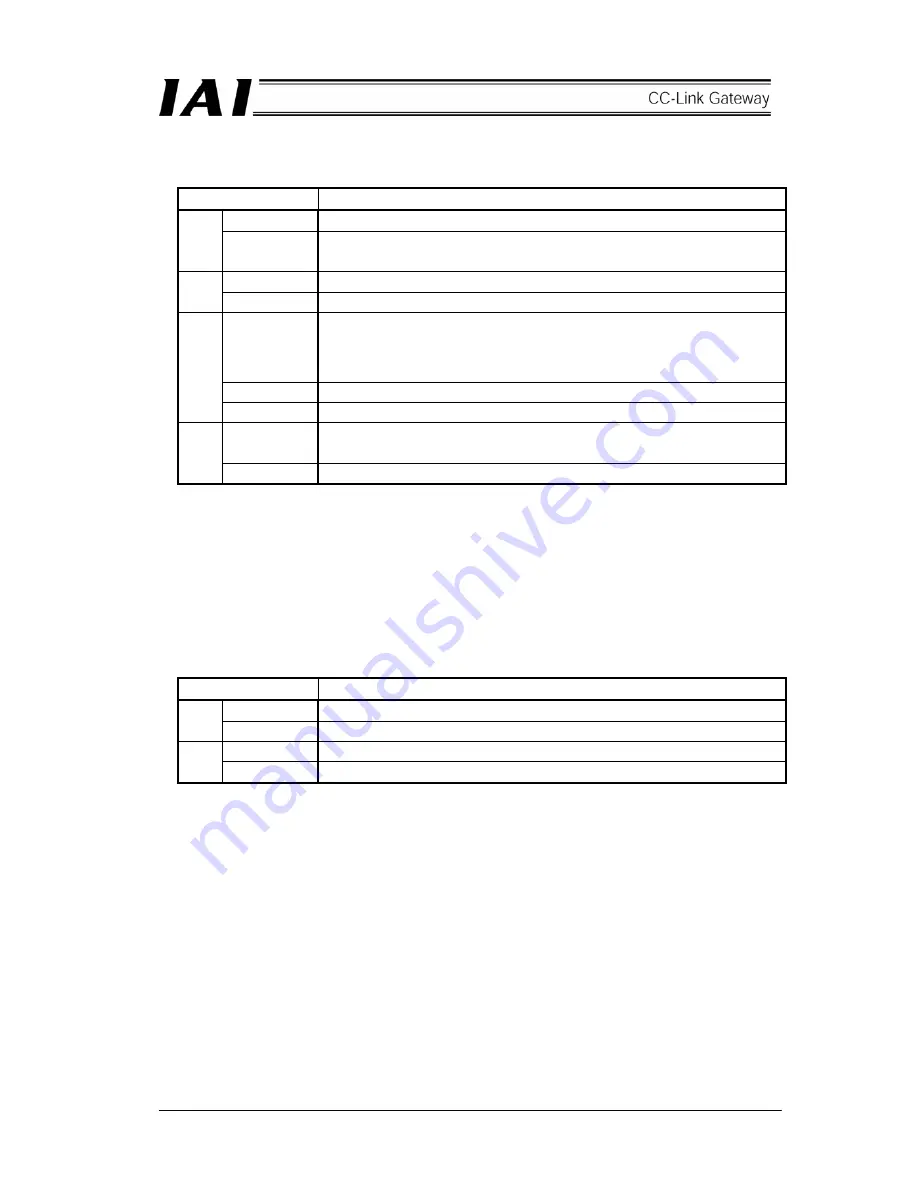
[1] Gateway status indication LED
Indicating status
Description
Lit in green
Indicates that the CPU of the gateway is operating.
RUN
Unlit
Indicates CPU operation stop status, and indicates that there is an error in the
CPU of the gateway when this is not lit even if power is turned on.
Lit in red
Gateway CPU is in error, major fault stop status.
G.ER
Unlit Normal
Lit in red
A status that CC-Link is in error, or CC-Link connection is not recognized from
the gateway CPU. (Check CC-Link communication status in [8].)
It is necessary to connect the teaching box or personal computer supporting
software if the RUN is lit even when this LED is lit.
Flash in red
This flashes at an interval of one second in the case of port on status.
C.ER
Unlit Normal
Lit in red
Communication error occurs in communication between the CC-Link gateway
and controller (No response, overrun, framing error or CRC(*) error) Normal
T.ER
Unlit Normal
* CRC: Cyclic Redundancy Check
Data error detecting method which is mostly used for synchronizing transmission
[2] SIO communication status LED
Communication status between CC-Link gateway and controller can be checked.
This LED flashes when communication between the upper PLC and controller is being performed through
CC-Link gateway, or communication is being performed with the controller by connecting the teaching box
or personal computer supporting software to the CC-Link gateway.
Indicating status
Description
Flash in green Data is transmitting (from the CC-Link gateway to controller)
TxD
Unlit
Data transmission is suspended (from the CC-Link gateway to controller)
Flash in green Data is receiving (from controller to the CC-Link gateway)
RxD
Unlit
Data reception is suspended (from controller to the CC-Link gateway)
Summary of Contents for CC-Link
Page 1: ...IAI America Inc CC Link RCM GW CC Gateway Unit Operation ManualFirst Edition ...
Page 4: ......
Page 10: ...6 1 5 How to identify model RCM GW CC Basic model For CC Link Gateway unit ...
Page 12: ...8 2 2 External dimension drawing Mounting dimension ...
Page 78: ...74 ...
Page 82: ...78 Position data measurement value Present position 1 2 3 4 4 5 6 7 ...
Page 84: ...80 Speed acceleration and deceleration set value Actuator speed Speed n2 Speed n3 1 2 3 ...
Page 88: ...84 Command position No Completion position No 1 2 3 4 5 6 ...
Page 91: ...87 ...
Page 93: ...89 ...
Page 125: ...121 No 3 Axis 1 pause No 3 Axis 1 pause lamp No 3 Axis 1 STP ...
Page 130: ...126 ...
Page 131: ......


