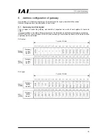
46
[List of alarm content]
This list shows alarm content to be outputted (binary code) in PM8 to PM1 while an alarm occurring. For
details of alarm content, refer to the Operation Manual for the controller.
○
: ON
×
: OFF
ALM PM8 PM4 PM2 PM1
Output
code
Contents Remarks
×
- - - -
- Normal
○
×
×
×
○
1
For manufacturer
*
○
×
×
○
×
2
For manufacturer
*
○
×
×
○
○
3
Moving command in servo off status (80)
Position command in home return
non-completion status (82)
Absolute position moving command in
home return non-completion status (83)
Moving command in home return
executing (84)
○
×
○
×
×
4
PCB inconsistency error (F4)
○
×
○
×
○
5
Non-volatile memory writing abnormality
(F7)
*
○
×
○
○
×
6
Parameter data abnormality (A1)
Position data abnormality (A2)
Position command information data
abnormality (A3)
○
×
○
○
○
7
Excitation detection error (B8)
Operation time time-out in home return
operation (BE)
○
○
×
×
×
8
Actual speed excessively large (C0)
○
○
×
×
○
9
Overvoltage (C9)
Overheat (CA)
Control power voltage abnormality (CC)
Control power voltage drop (CE)
○
○
×
○
×
A
For manufacturer
*
○
○
×
○
○
B
Position deviation counter overflow (D8)
○
○
○
×
×
C
Servo abnormality (C1)
○
○
○
×
○
D
A, B phase breakage (E8)
A phase breakage (E9)
B phase breakage (E9)
RCP2 absolute encoder abnormality
detection 1 (ED)
RCP2 absolute encoder abnormality
detection 2 (EE)
RCP2 absolute encoder abnormality
detection 3 (EF)
○
○
○
○
×
E
CPU abnormality (FA)
FPGA abnormality (FB)
○
○
○
○
○
F
Non-volatile memory writing times over
(F5)
Non-volatile memory writing time-out (F6)
Non-volatile memory data destruction
(F8)
Insides of parentheses represent alarm codes indicated by personal computer supporting software or teaching
box.
* Error which never occurs when gateway is used
Summary of Contents for CC-Link
Page 1: ...IAI America Inc CC Link RCM GW CC Gateway Unit Operation ManualFirst Edition ...
Page 4: ......
Page 10: ...6 1 5 How to identify model RCM GW CC Basic model For CC Link Gateway unit ...
Page 12: ...8 2 2 External dimension drawing Mounting dimension ...
Page 78: ...74 ...
Page 82: ...78 Position data measurement value Present position 1 2 3 4 4 5 6 7 ...
Page 84: ...80 Speed acceleration and deceleration set value Actuator speed Speed n2 Speed n3 1 2 3 ...
Page 88: ...84 Command position No Completion position No 1 2 3 4 5 6 ...
Page 91: ...87 ...
Page 93: ...89 ...
Page 125: ...121 No 3 Axis 1 pause No 3 Axis 1 pause lamp No 3 Axis 1 STP ...
Page 130: ...126 ...
Page 131: ......


