Motion Overview
406
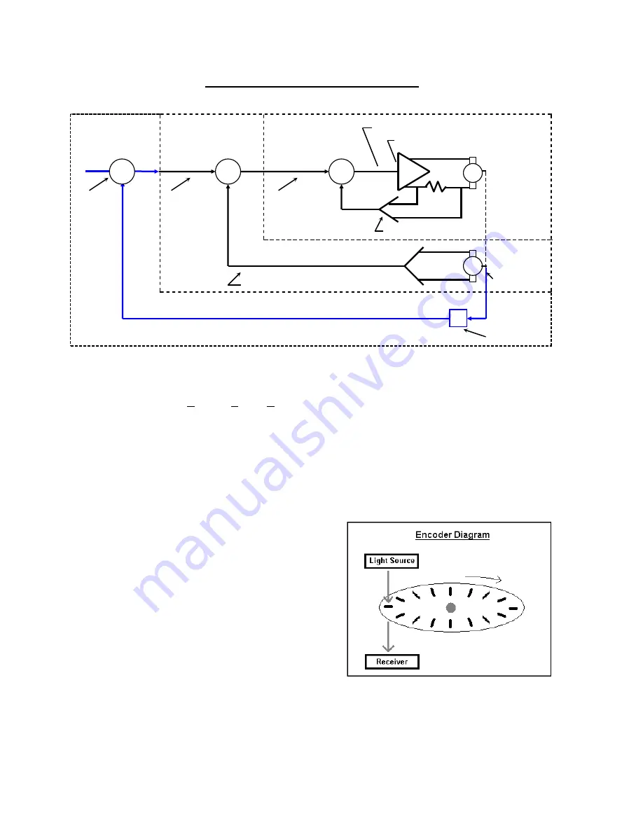
Typical Velocity and Position Loop System
The Motion Command starts as Digital Output within the control and then is converted to a +/- 10VDC
Analog Output for use by the motors. This conversion of the Motion Command within the control is
referred to as the DAC (Digital to Analog Converter) Output and is performed by the Motion Control
Card. The Analog Output when it comes out of the control is sent to a drive amplifier that then steps
up the voltage output to the motor and creates motion. Also, there is usually a linear relationship
between the voltage sent and the machine speed (i.e. 10 volts = maximum machine speed, 5 volts =
half max machine speed). Additionally, the polarity of the output (DAC Po/-) to the amplifier
will dictate the direction of the motor rotation. In most applications and in the following application
description the feedback device is an Encoder.
1a) What is an Encoder?
Essentially, an Encoder is a feedback device
that provides signal pulses as the motor turns.
The diagram at the right illustrates the basic
concept of an Encoder. Although this does
not represent all Encoder / feedback device
technology, this illustration provides a visual
aid to help understand the process.
The illustration shows a disk with small holes
cut out along the outer edge. The light source
provides a beam of light projected downward
through the holes in the disk. As the disk
turns on the end of the motor shaft, the light passes through the disk creating pulses.
The Receiver below the disk picks up the pulsed light source and sends that
feedback to the control.
Current
Command or
Velocity Error
Signal
Velocity
Command
Signal
Servo
Motor
Current Amplifier
Current Error Signal
Current
Feedback
Tachometer
Velocity
Loop
Current
Loop
Position
Loop
E
Position
Command
Encoder
+
-
Velocity Feedback Signal
+
+
-
-
M
T
R
S
Summary of Contents for Edge TI
Page 24: ...Table of Contents XXII...
Page 41: ...Overview 17 Alpha Numeric Keypad Numeric Keypad...
Page 54: ...Overview 30...
Page 83: ...Setups 59 Water Jet Press the Timing Diagram soft key to view the timing diagram from setups...
Page 88: ...Setups 64...
Page 116: ...Shape Manager 92...
Page 128: ...Files 104...
Page 280: ...Part Options 256...
Page 317: ...Diagnostics 293 DriveTop from Indramat...
Page 402: ...Phoenix Link 378...
Page 420: ...Sensor THC 396...
Page 428: ...Command THC 404...
Page 436: ...Motion Overview 412 Motion Tuning Watch Windows Position and Following Error may be displayed...
Page 470: ...Program Codes 446...
Page 478: ...Automated Plasma Interface 454 Inputs...
Page 479: ...Automated Plasma Interface 455 Inputs...
Page 480: ...Automated Plasma Interface 456 Outputs...
Page 496: ...Automated Plasma Interface 472...
Page 520: ...MicroEdge 496...
Page 532: ...Edge Ti 508 Optional Motor Information...
Page 540: ...Edge Ti 516...
Page 546: ...Voyager III 522 Examples of possible circuits Output Input 24 VDC Com...
Page 557: ...Networking 533 7 Double Click on the network interface connected to your LAN...
Page 558: ...Networking 534...
Page 561: ...Networking 537...
Page 562: ...Networking 538 13 Double click on the System 14 Select the Computer Name tab...
Page 572: ...Networking 548...
Page 573: ......


