


70
8
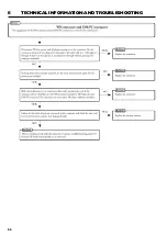
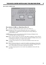
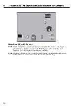
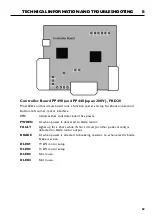
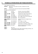
TECHNICAL INFORMATION AND TROUBLESHOOTING
Lower middle, boost transformer.
BFAULT
Lights up for a short while if over power is detected in the boost
transformer.
BRUN
Lit when power is directed to the booster. Should follow PWREN.
Top right corner, boost transformer.
BLED1
BF_HW
Hardware trip, same fault as BFAULT.
BLED2
BF_PHASE
At least one phase missing, hardware.
BLED1 & BLED2
BF_TEMP
Temperature too high in boost transformer.
BLED3
BSF_PHASE
At least one phase missing, software.
BLED1 & BLED3
BSF_OVERVOLT
Over voltage internally in boost transformer.
BLED2 & BLED3
BSF_OVERCURR
Over current, software.
BLED1, BLED2 &
BSF_OVERLOAD
Overload, blade motor is taking too much
BLED3
current.
BLED4
BSF_OVERINPUT Over voltage on incoming.
BLED1 & BLED4
BSF_AUTOCAL
Unsuccessful automatic calibration.
BLED2 & BLED4
BSF_TIMING
Internal timer error. Software or MCU broken.
BLED1, BLED2 &
BSF_D2D I
nternal communication error. Most likely
LED4
broken
controller
board.
BLED5
Not in use.
BLED6
Indicates if booster tries to take more than 32 Amp (or 25 Amp or 16
Amp depending on setting) from the grid.
Summary of Contents for PP440HF
Page 1: ...HUSQVARNA CONSTRUCTION PRODUCTS Workshop manual WS440HF WS482HF PP440HF PP480HF PP490HF ...
Page 2: ...2 LEGEND ...
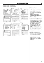
Page 43: ...8 43 TECHNICAL INFORMATION AND TROUBLESHOOTING Function test Remote Control p 22 ...
Page 44: ...44 8 TECHNICAL INFORMATION AND TROUBLESHOOTING Power Supply p 46 ...
Page 52: ...52 8 TECHNICAL INFORMATION AND TROUBLESHOOTING Internal water valve p 62 ...
Page 55: ...8 55 TECHNICAL INFORMATION AND TROUBLESHOOTING ...
Page 56: ...56 8 TECHNICAL INFORMATION AND TROUBLESHOOTING ...
Page 58: ...58 8 TECHNICAL INFORMATION AND TROUBLESHOOTING ...
Page 60: ...60 8 TECHNICAL INFORMATION AND TROUBLESHOOTING ...
Page 65: ...8 65 TECHNICAL INFORMATION AND TROUBLESHOOTING ...
Page 66: ...66 8 TECHNICAL INFORMATION AND TROUBLESHOOTING ...
Page 156: ...1 5 6 13 WIRING DIAGRAMS 13 WIRING DIAGRAMS Electrical Drawings WS482 Saw Head Circuit Board ...
Page 157: ...13 1 5 7 WIRING DIAGRAMS PP480 ...
Page 158: ...1 5 8 13 WIRING DIAGRAMS PP490 4 pin ...
Page 159: ...13 1 5 9 WIRING DIAGRAMS PP490 5 pin ...
Page 161: ...13 1 6 1 WIRING DIAGRAMS PP490 ...
Page 162: ...1 6 2 13 WIRING DIAGRAMS Remote Control ...
Page 164: ...1 6 4 13 WIRING DIAGRAMS Contact connected to PP 480 440 HF Straight connection ...
Page 165: ...www husqvarnacp com 115 84 14 26 English 2013 04 ...