background image

OPERATION

16

Further Operation and Programming Information

PowerView

®

 Pebble

®

 Remote and/or PowerView

®

 Surface Remote 

Operation

For information regarding operation and programming of the PowerView

®

 remote, refer to your 

PowerView

®

 Motorization Remote Control Guide

 or to the online PowerView Step-by-Step 

Guide at 

hunterdouglas.com/operating-systems/motorized/powerview-motorization/

manuals

.

PowerView

®

 Scene Controller

For information regarding operation and programming of the PowerView

®

 Scene Controller, 

refer to your 

PowerView Motorization Scene Controller Guide

 or to the online PowerView 

Step-by-Step Guide at 

hunterdouglas.com/operating-systems/motorized/powerview-

motorization/manuals

.

PowerView

®

 App Operation

The PowerView

®

 Hub is required for PowerView

®

 App operation. For information regarding 

setup and operation using the PowerView App, refer to the online PowerView Step-by-Step 
Guide at 

hunterdouglas.com/operating-systems/motorized/powerview-motorization/

manuals

.

Resetting the Shading (If Necessary)

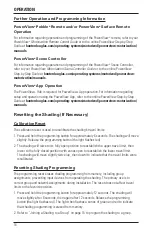
Calibration Reset

The calibration reset is used to recalibrate the shading’s travel limits.
1. Press and hold the programming button for approximately 6 seconds. The shading will move 

slightly. Release the programming button (the light flashes red).

2. The shading will raise to its fully open position to reestablish the upper travel limit, then 

lower to the fully closed position with vanes open to reestablish the lower travel limit. 
The shading will move slightly twice (up, then down) to indicate that the travel limits were 
recalibrated.

Resetting Shading Programming

The programming reset erases shading programming from memory, including group 
assignments, preventing input devices from operating the shading. The primary use is to 
correct group and network assignments during installation. The reset does not affect travel 
limits or the favorite position.
1. Press and hold the programming button for approximately 12 seconds. The shading will 

move slightly after 6 seconds, then again after 12 seconds. Release the programming 
button (the light flashes red). The light then flashes a series of green and red to indicate 
that shading programming is erased from memory.

2. Refer to “Joining a Shading to a Group” on page 15 to program the shading to a group.

Summary of Contents for Pirouette PowerView

Page 1: ...Installation Operation Care Pirouette Window Shadings PowerView Motorization...

Page 2: ...ttery Wand If Applicable 9 STEP 3 Install the Shading 10 STEP 4 Connect the Power Source If Applicable 11 OPERATION Testing the Shading 14 Using the PowerView Remote 14 Resetting the Shading If Necess...

Page 3: ...D 1 Product View Installation Brackets Fabric covered Headrail Fabric Headrail End Cap Programming Button Battery Wand Bottom Rail Optional Dust Cover For Outside Mount Optional Back Cover For Inside...

Page 4: ...t Provided If using spacer blocks use 6 screws long enough for a secure attachment Speed Nuts and Screws Provided Extension brackets come with screws and speed nuts Drywall Anchors Not Provided Use dr...

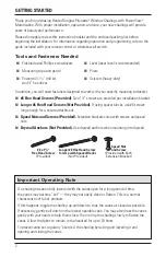
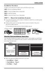
Page 5: ...ckets are used for end mount shadings as well Mounting Types and Window Terminology If the installation brackets are mounted correctly the rest of the installation process follows easily To prepare fo...

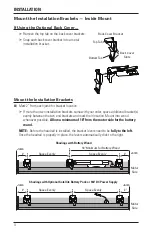
Page 6: ...o end brackets and mark their location Mount into wood whenever possible Allow a minimum of 18 from the motor side for the battery wand NOTE Before the headrail is installed the bracket levers need to...

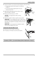
Page 7: ...ting into drywall Attach the installation brackets using the screws provided IMPORTANT Do not overtighten the screws Check to ensure the bracket lever can be moved easily side to side If not loosen th...

Page 8: ...ide for the battery wand NOTE Before the headrail is installed the bracket levers need to be fully to the left Once the headrail is properly in place the levers automatically click to the right Center...

Page 9: ...unting surface with 6 screws long enough for a secure installation The top of the spacer blocks should be at the desired shading height IMPORTANT Do not add more than 11 2 of clearance using spacer bl...

Page 10: ...lation brackets to the extension brackets using the provided screws and speed nuts IMPORTANT On the motor side the installation bracket must be attached at the end of extension bracket WARNING To end...

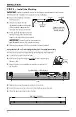
Page 11: ...power cable from the motor side into the socket on the battery wand NOTE When power is connected to the motor a green LED in the bottom of the control side end cap will flash to indicate the shading i...

Page 12: ...bracket to ensure it is installed securely Remove the protective film from the fabric covered headrail Attach the Dust Cover Optional for Outside Mounts The dust cover is used to protect the top of th...

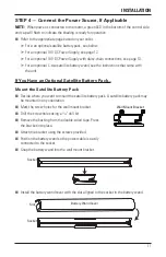
Page 13: ...that came with the unit If You Have an Optional Satellite Battery Pack Mount the Satellite Battery Pack Decide where you want to mount the satellite battery pack A satellite battery pack may be mount...

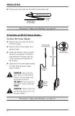
Page 14: ...make sure it does not impede the operation of the shading Space the wire retainers approximately 15 apart along the power supply cable as shown WARNING Keep cords and small parts out of the reach of c...

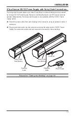
Page 15: ...sy chain feature is only available with the 18V DC Power Supply option Route the power cables from each shading to the connector using an extension cable if necessary Plug an extension cable into the...

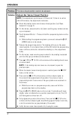
Page 16: ...ail It should roll up evenly If the bottom rail is not level or the shading starts to rub against either window jamb immediately press the programming button to stop the shading See Adjusting the Bott...

Page 17: ...Press all or groups 1 6 to select specific shading s to move Selected group button s will light to show they are selected Multiple group buttons may be selected at a time To deselect a group press the...

Page 18: ...The calibration reset is used to recalibrate the shading s travel limits 1 Press and hold the programming button for approximately 6 seconds The shading will move slightly Release the programming butt...

Page 19: ...ble from the motor then plug it back in A green LED inside the programming button housing should flash to indicate the motor has power Check that the batteries in the battery wand satellite battery pa...

Page 20: ...lowest operable vane Problem The bottom rail does not raise completely or lower completely or its location when fully lowered has migrated over time Solution The batteries may be low in the battery w...

Page 21: ...l If uneven see Adjusting the Bottom Rail Weight on page 23 Problem The vanes do not close completely They stay contoured and do not flatten Solution Toggle the vanes open and closed then coax the van...

Page 22: ...he shading is selected and the other group numbers are de selected Press OPEN or CLOSE on the remote and the shading should move at a slow speed NOTE If the shading does not move at a slow speed repea...

Page 23: ...the shading is selected and the other group numbers are de selected Press OPEN or CLOSE on the remote and the shading should move at a slow speed NOTE If the shading does not move at a slow speed rep...

Page 24: ...r the shading is selected and the other group numbers are de selected Press OPEN or CLOSE on the remote and the shading should move at a slow speed NOTE If the shading does not move at a slow speed re...

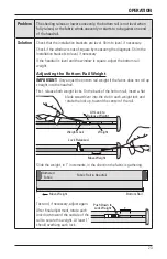
Page 25: ...ht IMPORTANT Only adjust the bottom rail weight if the fabric does not roll up straight into the headrail First release both weight locks On the back of the bottom rail insert a flat blade screwdriver...

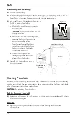
Page 26: ...tom of the bracket between the screw holes Push the tab away from the shading and pull the headrail to release it from the bracket Carefully pull the shading to remove it from the brackets Cleaning Pr...

Page 27: ...mild detergent solution be used Never immerse the headrail in the solution Allow the shading to dry in the completely lowered position Electrostatic Cleaning Do not use electrostatic cleaning devices...

Page 28: ...r an uncontrolled environment and meets the FCC radio frequency RF Exposure Guidelines This equipment should be installed and operated keeping the radiator at least 20 cm or more away from person s bo...

Page 29: ...Notes...

Page 30: ...Notes...

Page 31: ......

Page 32: ...ponents are covered for 5 years from the date of purchase 1 Contact your original dealer place of purchase for warranty assistance 2 Visit hunterdouglas com for additional warranty information frequen...

Reviews: