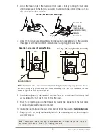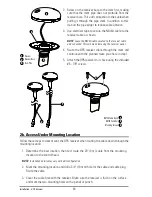
4. Move the receiver to the side and drill two pilot holes using a 9/64" (3.5 mm) bit.
NOTE
: Remember to seal screw holes and drilled holes as needed with marine-grade silicone sealant to
protect your boat from water damage.
5. Align the GPS receiver screw holes over the pilot screw holes and attach with the
#8 - 1 1/4" Phillips head screws.
Hand tighten only!
NOTE:
If the mounting surface is thin and made of a lighter material, a backing material may be needed
below the mounting surface.
2c. No Access Under Mounting Location
Follow these steps to deck mount the GPS receiver in a situation where you must route the cable
to the side because there is no space for a cable underneath the mounting location.
1. Determine the best location, then test route the cable from the mounting location to the
control head.
NOTE:
AS-EC10 10' extension cables are available from Humminbird® if your planned routing exceeds 20',
(6 m). Maximum cable length, including extensions, should not exceed 50' (16 m).
2. Confirm the cable length is good and route the cable from the receiver to the control
head. If holes are required to route the cable, they must be 3/4" (19 mm) to allow for
the cable connector. Secure the NMEA cable with electrical tape.
NOTE:
Remember to seal screw holes and drilled holes as needed with marine-grade silicone sealant to
protect your boat from water damage.
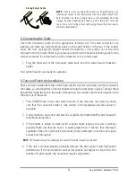
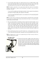
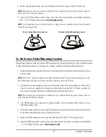
3. The GPS receiver has two wire routing notches. Use the cable notch closest to the
intended cable route.
4. With the cable routed, position the GPS receiver in the planned mounting location and
mark the mounting holes with a pencil or punch.
5. Move the GPS receiver to the side and drill the two 9/64" (3.5 mm) pilot holes.
6. Align the GPS receiver's screw holes over the pilot screw holes and attach with the #8
- 1 1/4" Phillips head screws.
Hand tighten only!
Access Under Mounting Location
No Access Under Mounting Location
47
Installation - GPS Receiver
Summary of Contents for 1158c Combo
Page 1: ...Installation and Operations Manual 1158c Combo 1198c SI Combo Product Manual...
Page 73: ...61 to your boat including the following items What s on the Sonar Display 7 10 3 4 5 6 11...
Page 146: ...Sonar Tab Normal Mode Sonar Tab Advanced Mode Menu Quick Tips 134...


