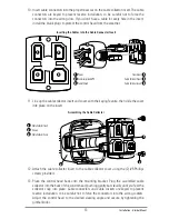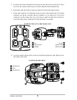
10. Insert cable connectors into the proper recesses on the cable collector insert. The cable
connectors are keyed to prevent reverse installation, so be careful not to force the
connectors into the wrong slots. If you don’t have a cable for every hole in the insert,
install the blank plugs to protect the control head from the weather.
11. Line up the cable collector insert and cover, with the keying feature, then slide the cover
into place on the insert.
12. Attach the cable collector insert to the cable collector cover using the (2) #6 Phillips
screws provided.
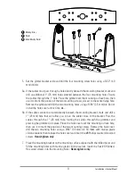
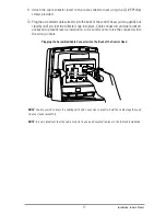
13. Place the control head back onto the mounting bracket. Plug the assembled cable
collector into the back of the control head, pushing gently but steadily until you feel the
collector snap into place. Cable connectors and cable sockets are keyed to prevent
reverse installation, so be careful not to force the connectors into the wrong sockets.
Adjust the control head to the desired viewing angle and secure by tightening the
gimbal knobs.
Cable Collector Insert
1
Screws
2
Cable Collector Cover
3
Assembling the Cable Collector
3
1
2
Transducer
Cable Collector Cover
4
5
Cable Collector Insert
6
Inserting the Cables into the Cable Connector Insert
1
2
3
4
Power
Communications/GPS
1
2
Temp/Speed
3
5
6
13
Installation - Gimbal Mount
Summary of Contents for 1158c Combo
Page 1: ...Installation and Operations Manual 1158c Combo 1198c SI Combo Product Manual...
Page 73: ...61 to your boat including the following items What s on the Sonar Display 7 10 3 4 5 6 11...
Page 146: ...Sonar Tab Normal Mode Sonar Tab Advanced Mode Menu Quick Tips 134...

