


1022410 – 0001 Rev. 2
5–14 Hardware installation
This section describes testing the UMOD to verify that it is
operational.
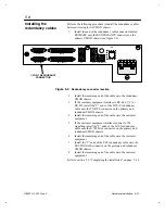
1.
Set the O/| power switch to | (activated).
Upon startup, the LED on the UMOD board will begin
cycling through a series of codes as the UMOD initializes
its internal components and performs full-function
diagnostics self-tests.
Table 5-3
UMOD startup tests
LED Display
Definition
Random access memory (RAM) test. This test
writes a value to all RAM addresses, and veri-
fies that the value can be read correctly.
Central processing unit (CPU) test. This test
examines the microprocessor on the UMOD
board
Internal timer test. This test examines the inter-
nal control processor timers.
DMA test. This test examines the direct
memory access function.
Q-UART test. This test verifies that the quad-
universal asynchronous receiver/transmitter
(Q-UART) is functional.
SCC test. This test verifies that the serial com-
munications controller (SCC) is functional.
SCC DMA test. This test verifies DMA access
to the SCC.
PIC test. This test examines the internal PIC.
NVRAM test. This test computes the checksum
for the non-volatile random-access memory
(NVRAM) and compares it to the checksum
stored in the last two bytes of NVRAM memory.
Flash code verification. This test verifies that
the flash memory has not been corrupted by
calculating the checksum and comparing the
result to the stored value.
Full-function diagnostic. This test performs a
full-function diagnostics test of the UMOD
board. The internal bit error rate (BER) tester
sends data through the transmit and receive
circuitry, including the terrestrial data interface
daughtercard (either a DIM or GIM), and the
optional internal framing unit (IFU).
If the tests are successful, you will see the sequence of
displays on the card’s LED as presented in table 5-3 .
Each is a solid display, not flashing. The presence of a dot
indicates that the UMOD board failed a test.
5.9
Completing the
installation