


1022410 – 0001 Rev. 2
5–12 Hardware installation
Note
If you are using the redundancy option, both UMOD chassis must be
set to the same ID code. (For example, if the primary UMOD ID code
is 6EB1, the redundant UMOD would also be 6EB1.)
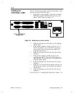
1.
Using a 1/4-inch flat-blade screwdriver, set switch S1 to the
same setting as the first (leftmost) hexadecimal digit in your
chassis ID code. In the example this number would be 6.
Note
The maximum UMOD chassis code setting is 7FFF, therefore switch S1
cannot be set to a higher setting than 7. Switches S2 thru S4 can each
be set as high as F.
2.
Set switch S2 to the same setting as the second digit in the
code. In the example this number would be E.
3.
Set switch S3 to the same setting as the third digit. In the
example this number would be B.
4.
Set switch S4 to the same setting as the fourth digit. In the
example this number would be 1.
If your UMOD will be connected to a redundant UMOD chassis,
refer to section 5.8, “Installing the redundancy cable” on
page 5–13. Otherwise, refer to section 5.9, “Completing the
installation” on page 5–14.